U1 - 72 – Yaskawa R1000 Series Power Regenerative Unit User Manual
Page 170
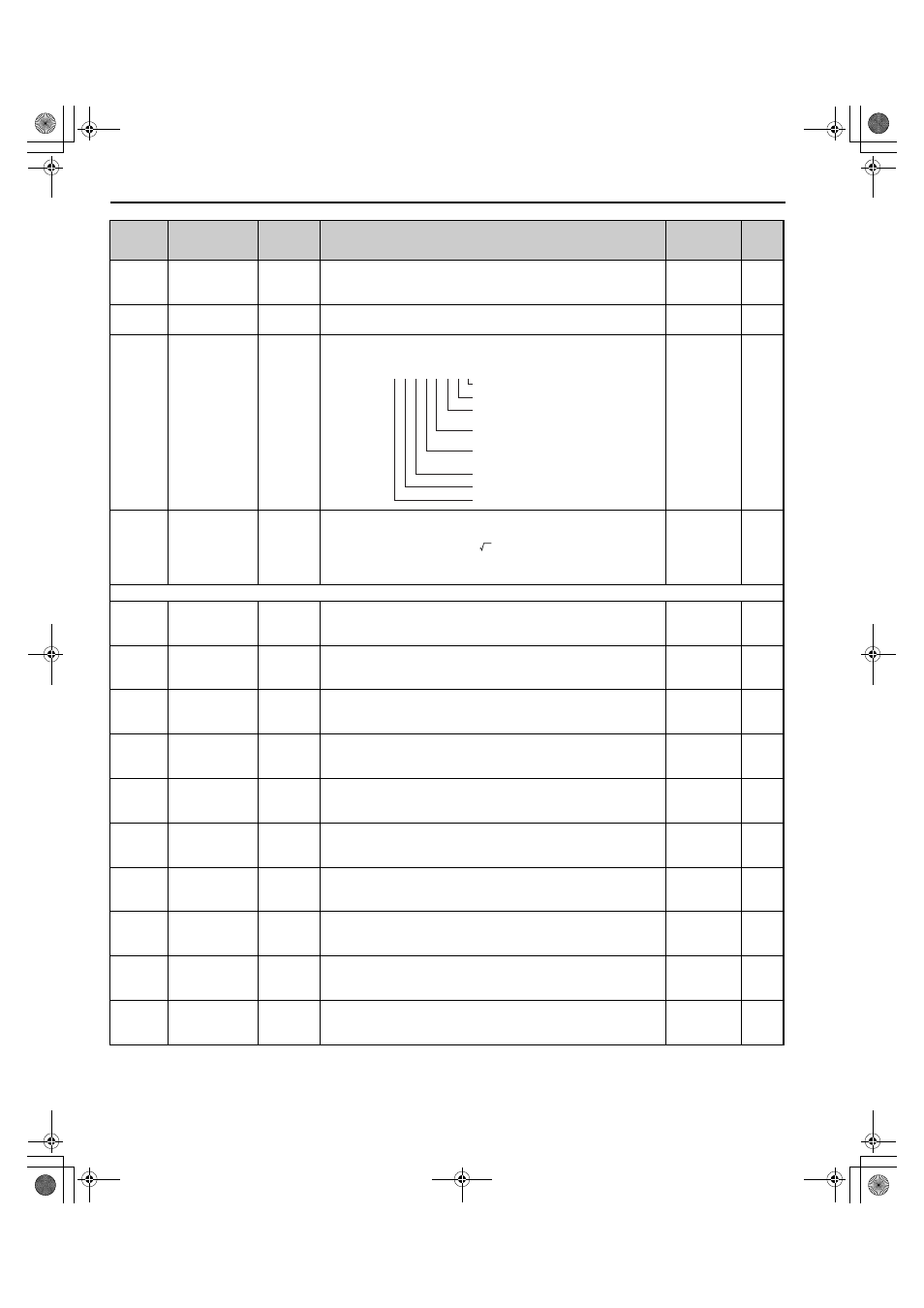
B.2 Parameter Tables
170
YASKAWA ELECTRIC TOEP C710656 08B YASKAWA Power Regenerative Unit - R1000 Instruction Manual
U1-57
(1086H)
Power Supply
Side Power
AC Power Shows the power on the power supply side.
10 V: Rated
power (input
side)
1 kW
U1-58
(1087H)
Power Supply
Frequency
AC
Frequency
Shows the frequency on the power supply side.
10 V: Rated
Frequency
0.1 Hz
U1-72
(1095H)
Input Power
Supply
Information
AC Supply
Status
Shows information on the input power supply.
No signal
output
available
–
U1-73
(1096H)
Voltage Deviation V deviation
Shows the deviation between the DC bus voltage and the power supply
voltage.
Deviation = Bus voltage (U1-52)
– Power supply voltage (U1-54)
If automatic operation is enabled, operation starts when the voltage
increases to this value
No signal
output
available
1
U2: Fault Trace
U2-01
(80H)
Current Fault
Current
Fault
Displays the current fault.
No signal
output
available
–
U2-02
(81H)
Previous Fault
Last Fault
Displays the previous fault.
No signal
output
available
–
U2-11
(8AH)
Input Terminal
Status at Previous
Fault
Input Term
Sts
Displays the input terminal status at the previous fault. Displayed as in
U1-10.
No signal
output
available
–
U2-12
(8BH)
Output Terminal
Status at Previous
Fault
Output
Term Sts
Displays the output status at the previous fault. Displays the same status
displayed in U1-11.
No signal
output
available
–
U2-13
(8CH)
Drive Operation
Status at Previous
Fault
Inverter
Status
Displays the operation status of the regenerative unit at the previous fault.
Displays the same status displayed in U1-12.
No signal
output
available
–
U2-14
(8DH)
Cumulative
Operation Time at
Previous Fault
Elapsed
time
Displays the cumulative operation time at the previous fault.
No signal
output
available
1 h
U2-20
(8EH)
Heatsink
Temperature at
Previous Fault
Actual Fin
Temp
Displays the temperature of the heatsink when the most recent fault
occurred.
No signal
output
available
1
°C
U2-52
(841H)
DC Bus Voltage
Feedback at
Previous Fault
DC V
Feedback
Shows the DC bus voltage feedback value.
No signal
output
available
1 V
U2-54
(843H)
Power Supply
Voltage at
Previous Fault
AC Voltage Shows the power supply voltage.
No signal
output
available
1 V
U2-57
(846H)
Power Supply
Side Power at
Previous Fault
AC Power Shows the power on the power supply side.
No signal
output
available
1 kW
No.
(Address
Hex)
Name
LCD
Display
Description
Analog
Output
Level
Unit
U1 - 72=
0 0 0 0 0 0 0 0
Bit 0: AUv reset. (0: Not completed, 1: Reset)
Bit 1: PF3 reset (0: Not completed, 1: Reset)
Bit 2: Rated frequency detection
(0: Not completed, 1: Completed)
Bit 3: Phase order detection
(0: Not completed, 1: Completed)
Bit 4: Power supply established
(0: Not completed, 1: Completed)
Bit 5: Fdv detection (0: Not detected, 1: Detected)
Bit 6: PF3 detection (0: Not detected, 1: Detected)
Bit 7: Reserved.
2
TOEP_C710656_08B_1_0.book 170 ページ 2015年2月5日 木曜日 午前10時7分