Precautions and instructions for installation, Side-by-side installation with drive, Installation screws – Yaskawa R1000 Series Power Regenerative Unit User Manual
Page 27
2.2 Mechanical Installation
YASKAWA ELECTRIC TOEP C710656 08B YASKAWA Power Regenerative Unit - R1000 Instruction Manual
27
Mec
h
an
ic
al
In
st
al
la
tio
n
2
■
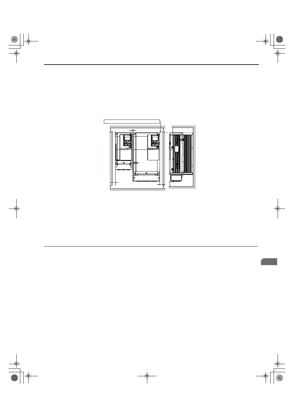
Side-by-Side Installation with Drive
Models 2A03P5 to 2A0028, 4A03P5 to 4A0028 can take advantage of Side-by-Side installation.
When installing the regenerative unit beside a drive, mount the devices according to
and set L8-35,
Installation Method Selection, to 1 (Side-by-Side Mounting).
When mounting regenerative units with the minimum clearance of 2 mm according to
, set parameter L8-35 to
1 while considering derating. Refer to
Figure 2.4
Figure 2.4 Space Between Regenerative Unit and Drive (Side-by-Side)
Note: Align the tops of the regenerative unit and the drives when installing the regenerative unit and the drives of different heights in the
same enclosure panel. Leave space between the tops and bottoms of stacked regenerative unit and drives for easier cooling fan
replacement.
■
Installation Screws
Exterior and Mounting Dimensions on page 30
for the sizes of the installation screws.
◆ Precautions and Instructions for Installation
Read the following precautions and instructions before installing models 2A0073, 2A0105, and 4A0210 to 4A0300.
WARNING! Crush Hazard. Observe the following instructions and precautions. Failure to comply could result in serious injury or death
from falling equipment.
• Only use vertical suspension to temporarily lift the regenerative unit during installation to an enclosure
panel.
• Do not use vertical suspension to transport the regenerative unit.
• Use screws to securely affix the regenerative unit front cover, terminal blocks, and other regenerative
unit components prior to vertical suspension.
• Do not subject the regenerative unit to vibration or impact greater than 1.96 m/s
2
(0.2 G) while it is
suspended by the wires.
• Do not attempt to flip the regenerative unit over while it is suspended by the wires.
• Do not leave the regenerative unit unattended while it is suspended by the wires.
A – 50 mm minimum
C – 2 mm minimum
B – 30 mm minimum
D – 120 mm minimum
A
A
A
A
B
C
B
D
D
Line up the tops of the drive and regenerative unit.
Side Clearance
Top/Bottom Clearance
Drive
Regenerative
Unit
YAI
TOEP_C710656_08B_1_0.book 27 ページ 2015年2月5日 木曜日 午前10時7分