4 powering up the regenerative unit, Powering up the regenerative unit, Status display – Yaskawa R1000 Series Power Regenerative Unit User Manual
Page 76
76
YASKAWA ELECTRIC TOEP C710656 08B YASKAWA Power Regenerative Unit - R1000 Instruction Manual
4.4 Powering Up the Regenerative Unit
4.4 Powering Up the Regenerative Unit
◆ Powering Up the Regenerative Unit and Operation Status Display
■
Powering Up the Regenerative Unit
Review the following checklist before turning the power on.
NOTICE: Equipment Damage. Check the following items before applying power to the unit. Failure to comply could result in damage to
the regenerative unit.
■
Status Display
When the power supply to the regenerative unit is turned on, the digital operator lights will appear as follows:
Item to Check
Description
Power supply voltage
Check the power supply voltage.
200 V class: Three-phase 200 to 240 Vac 50/60 Hz
400 V class: Three-phase 380 to 480 Vac 50/60 Hz
Properly wire the power supply input terminals (R/L1, S/L2, and T/L3).
Properly wire the phase order of the power supply input terminals (R/L1, S/L2, and T/L3) and the
power supply voltage detection terminals (
).
Check for proper grounding of regenerative unit.
Regenerative unit output terminals
and drive terminals
Properly connect the DC voltage output terminals ( / ) on the regenerative unit to the DC power
supply input terminals ( / ) on the drive. Be particularly careful to correctly connect the and
terminals.
Control circuit terminals
Properly connect the control circuit terminals on the regenerative unit to other control devices.
Regenerative unit control terminal
status
Turn off the Run Commands for the regenerative unit and the peripheral control devices.
Power coordinating reactor, current
suppression reactor, and fuse
connections to regenerative unit
Properly connect the Power coordinating reactor, current suppressoin reactor, and fuse to
regenerative unit as shown in the Standard Connection Diagram.
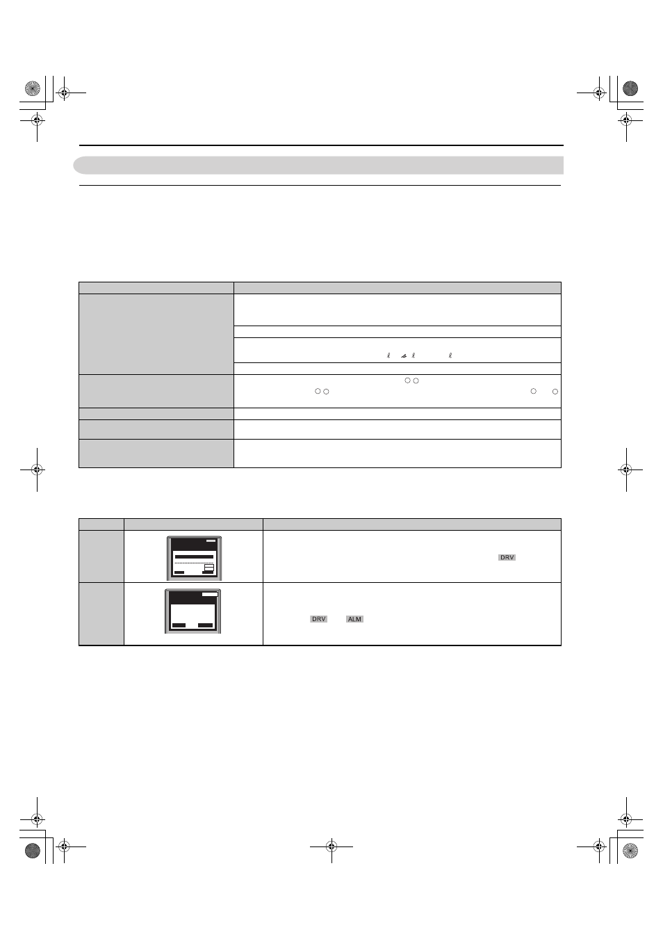
Status
Name
Description
Normal
Operation
The data display area displays the DC bus voltage feedback reference.
is lit.
Fault
Example: External Fault
Data displayed varies by the type of fault. Refer to
for more
information.
and
are
lit.
r1/ 11, 1/ 21, and t1/ 31
+ –
+ –
+
–
DIGITAL OPERATOR JVOP-180
ALARM
- MODE -
U1-55= 0A
U1-57= 0kW
U1-58=0.0Hz
DRV
AC Current
Rdy
RSEQ
RREF
YAI
DIGITAL OPERATOR JVOP-180
ALARM
- MODE -
EF3
Ext Fault S3
DRV
RESET
YAI
TOEP_C710656_08B_1_0.book 76 ページ 2015年2月5日 木曜日 午前10時7分