10 control i/o connections, Terminal a2 input signal selection, Refer to – Yaskawa R1000 Series Power Regenerative Unit User Manual
Page 63: Control i/o
3.10 Control I/O Connections
YASKAWA ELECTRIC TOEP C710656 08B YASKAWA Power Regenerative Unit - R1000 Instruction Manual
63
El
ec
tr
ical
I
n
st
al
lat
ion
3
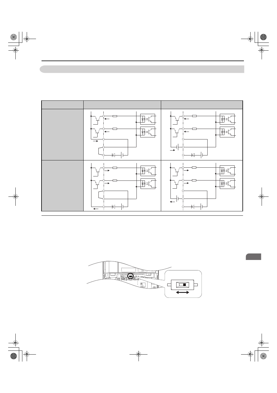
3.10 Control I/O Connections
Use the wire jumper between terminals SC and SP or SC and SN to select between Sink mode, Source mode or external
power supply for the digital inputs S1 to S8 as shown in
(Default: Sink mode, internal power supply).
Note: Never short terminals SP and SN as doing so will damage the regenerative unit.
Table 3.10 Digital Input Sink / Source / External Power Supply Selection
◆ Terminal A2 Input Signal Selection
Terminal A2 can be used to input either a voltage or a current signal. Select the signal type using switch S1 as explained
in
. Set parameter H3-09 accordingly as shown in
. Refer to
for locating switch S1.
To set the DIP switch, use tweezers or a tool with a tip width of approximately 0.8 mm.
Figure 3.25
Figure 3.28 DIP Switch S1
Regenerative Unit Internal Power Supply
(Terminal SN and SP)
External 24 Vdc Power Supply
Sinking Mode (NPN)
Sourcing Mode (PNP)
SC
S8
S7
24 Vdc
SP
SN
YAI
SC
S8
S7
24 Vdc
SP
SN
External
24 Vdc
YAI
SC
S8
S7
24 Vdc
SP
SN
YAI
SC
S8
S7
24 Vdc
SP
SN
External
24 Vdc
YAI
DIP switch S1
V
I
TOEP_C710656_08B_1_0.book 63 ページ 2015年2月5日 木曜日 午前10時7分