Wiring the control circuit terminal, For details on wiring, Table 3.9 – Yaskawa R1000 Series Power Regenerative Unit User Manual
Page 61: Ferrule-type wire terminals
3.9 Control Circuit Wiring
YASKAWA ELECTRIC TOEP C710656 08B YASKAWA Power Regenerative Unit - R1000 Instruction Manual
61
El
ec
tr
ical
I
n
st
al
lat
ion
3
■
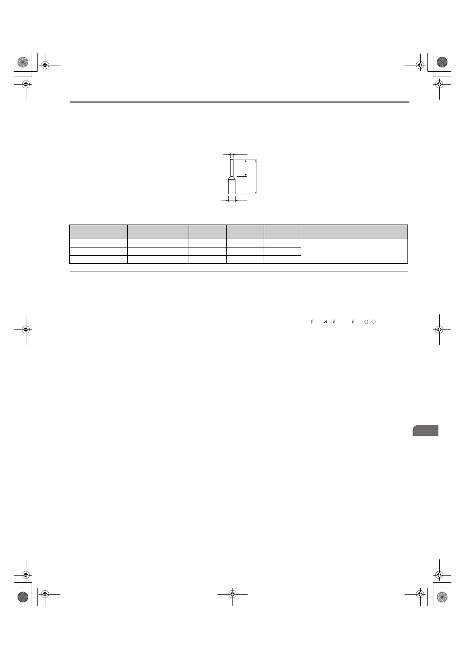
Ferrule-Type Wire Terminals
Yaskawa recommends using CRIMPFOX 6, a crimping tool manufactured by PHOENIX CONTACT, to prepare wire
ends with insulated sleeves before connecting to the regenerative unit. See
Figure 3.21
Figure 3.24 Ferrule Dimensions
Table 3.9 Ferrule Terminal Types and Sizes
◆ Wiring the Control Circuit Terminal
This section describes the proper procedures and preparations for wiring the control terminals.
WARNING! Electrical Shock Hazard. Do not remove covers or touch the circuit boards while the power is on. Failure to comply could
result in death or serious injury.
NOTICE: Separate control circuit wiring from main circuit wiring (terminals R/L1, S/L2, T/L3, r1/ 11, 1/ 21, t1/ 31, , ) and other
high-power lines. Improper wiring practices could result in regenerative unit malfunction due to electrical interference.
NOTICE: Separate wiring for digital output terminals MA, MB, MC, M1 to M6 from wiring to other control circuit lines. Improper wiring
practices could result in regenerative unit or equipment malfunction or nuisance trips.
NOTICE: Use a class 2 power supply (UL standard) when connecting to the control terminals. Improper application of peripheral
devices could result in regenerative unit performance degradation due to improper power supply.
NOTICE: Insulate shields with tape or shrink tubing to prevent contact with other signal lines and equipment. Improper wiring practices
could result in regenerative unit or equipment malfunction due to short circuit.
NOTICE: Connect the shield of shielded cable to the appropriate ground terminal. Improper equipment grounding could result in
regenerative unit or equipment malfunction or nuisance trips.
Wire the control circuit only after terminals have been properly grounded and main circuit wiring is complete.
Prepare the ends of the control circuit wiring as shown in
. Refer to
for the treatment of the ends
of the shield wire.
NOTICE: Do not tighten screws beyond the specified tightening torque. Failure to comply may result in erroneous operation, damage
to the terminal block, or cause a fire.
NOTICE: Use shielded twisted-pair cables as indicated to prevent operating faults. Failure to comply may cause electrical interference
resulting in poor system performance due to improper wiring practices. Use shielded, twisted-pair cables and ground the shield to the
shield ground terminal E (G) of the regenerative unit.
Size
mm
2
(AWG)
Type
L
(mm)
d1
(mm)
d2
(mm)
Manufacturer
0.25 (24)
AI 0.25–6YE
10.5
0.8
2
PHOENIX CONTACT
0.34 (22)
AI 0.34–6TQ
10.5
0.8
2
0.5 (20)
AI 0.5–6WH
14
1.1
2.5
φd1
φd2
6 mm
L
–
+
TOEP_C710656_08B_1_0.book 61 ページ 2015年2月5日 木曜日 午前10時7分