Control circuit terminal block functions – Yaskawa R1000 Series Power Regenerative Unit User Manual
Page 58
3.9 Control Circuit Wiring
58
YASKAWA ELECTRIC TOEP C710656 08B YASKAWA Power Regenerative Unit - R1000 Instruction Manual
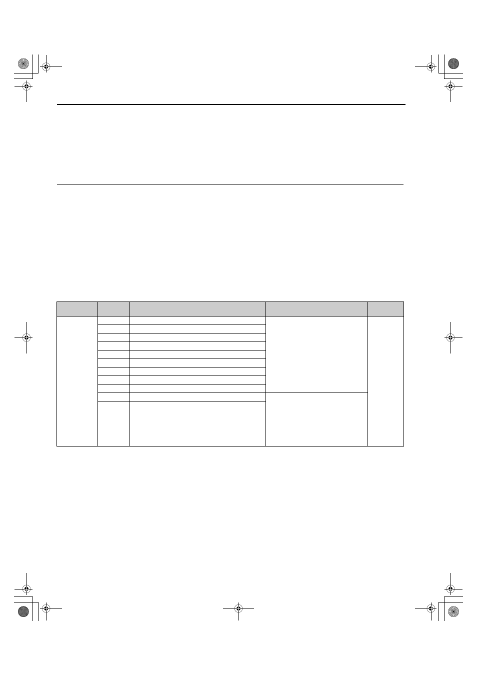
◆ Control Circuit Terminal Block Functions
Parameters determine which functions apply to the multi-function digital inputs (S1 to S8), multi-function relay outputs
(M1, M2, M3, M4, M5, M6), and multi-function analog monitor outputs (FM, AM). The default setting is listed next to
each terminal name in
.
NOTICE: Install an MC on the power supply side of the regenerative unit when the drive should not automatically restart after power
loss. To get the full performance life out of the electrolytic capacitors and circuit relays, refrain from switching the power supply off and
on more than once every 30 minutes. Frequent use can damage the regenerative unit.
■
Input Terminals
lists the input terminals on the regenerative unit. Text in parenthesis indicates the default setting for each
multi-function input.
Table 3.5 Control Circuit Input Terminals
<1> The default setting is for Sinking Mode. Control is possible with no-voltage contacts or NPN transistors. For details, refer to
Control I/O Connections on page 63
.
<2> The maximum output current capacity for the +V and -V terminals on the control circuit is 20 mA. Never short terminals +V, -V,
and AC, as it can cause erroneous operation or damage the regenerative unit.
<3> Set DIP switch S1 to select between a voltage or current input signal to terminal A2. The default setting is for current input. For
details, refer to
Terminal A2 Input Signal Selection on page 63
<4> Set DIP switch S2 to the ON position to enable the termination resistor in a MEMOBUS/Modbus network.
<5> Monitor outputs work with devices such as analog frequency meters, ammeters, voltmeters, and wattmeters. They are not intended
for use as a feedback-type signal.
Type
No.
Terminal Name (Function)
Function (Signal Level)
Default Setting
Page
Multi-Function
Digital Inputs
S1
Multi-function input 1 (Forced operation command)
• Photocoupler
• 24 Vdc, 8 mA
• Set the S3 jumper to select between
sinking, sourcing mode, and the power
supply. Refer to
.
S2
Multi-function input 2 (Automatic operation command)
S3
Multi-function input 3 (External fault)
S4
Multi-function input 4 (Fault reset)
S5
Multi-function input 5 (Reserved)
S6
Multi-function input 6 (Reserved)
S7
Multi-function input 7 (Reserved)
S8
Multi-function input 8 (External Baseblock)
SC
Multi-function input common
SP
Digital input power supply +24 Vdc
24 Vdc power supply for digital inputs,
150 mA max (only when not using digital
input option DI-A3)
NOTICE: Do not jumper or short
terminals SP and SN. Failure to
comply will damage the regenerative
unit.
SN
Digital input power supply 0 V
TOEP_C710656_08B_1_0.book 58 ページ 2015年2月5日 木曜日 午前10時7分