9 control circuit wiring, Control circuit wiring, Regenerative unit r1000 – Yaskawa R1000 Series Power Regenerative Unit User Manual
Page 57
3.9 Control Circuit Wiring
YASKAWA ELECTRIC TOEP C710656 08B YASKAWA Power Regenerative Unit - R1000 Instruction Manual
57
El
ec
tr
ical
I
n
st
al
lat
ion
3
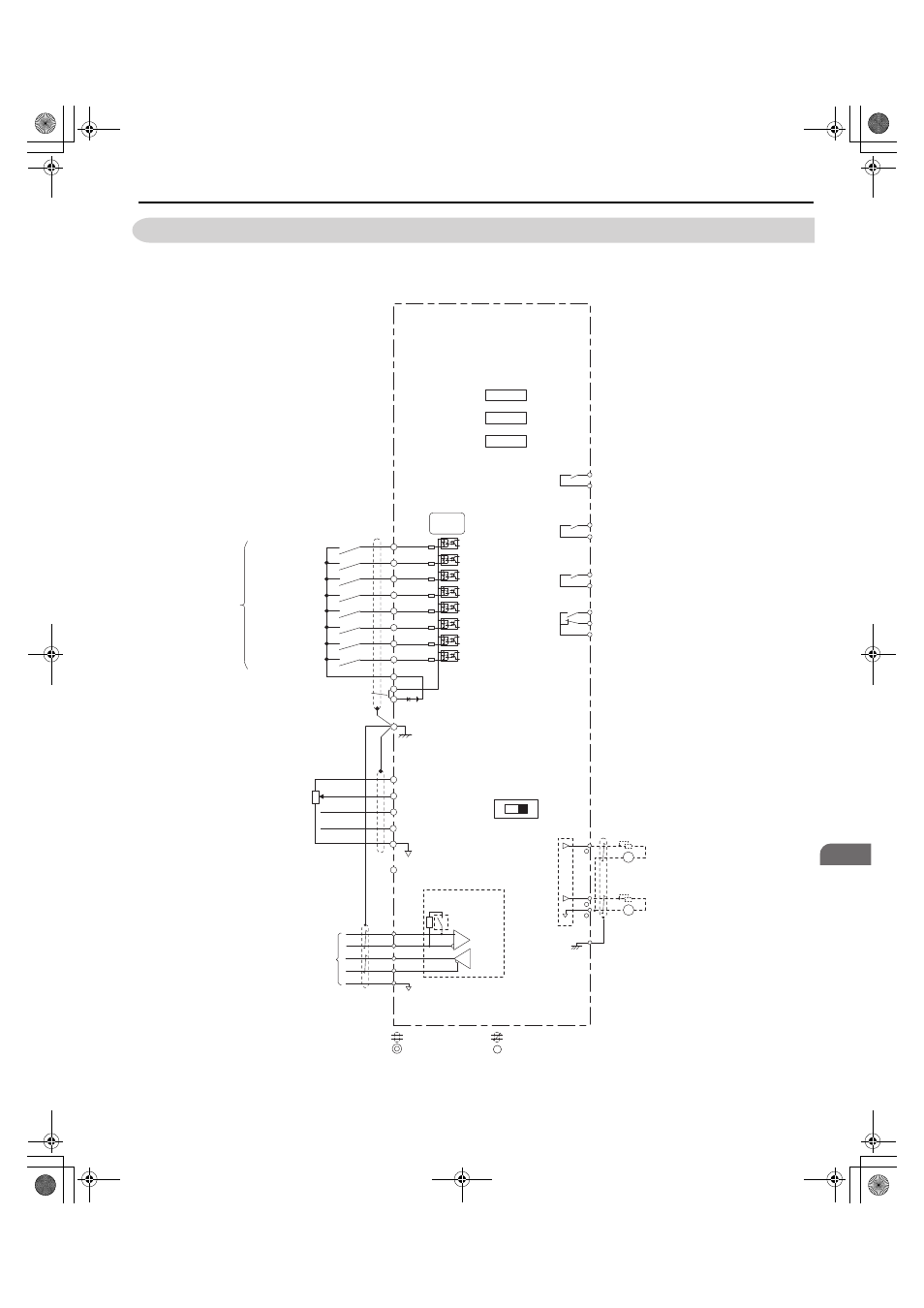
3.9 Control Circuit Wiring
NOTICE: Do not connect AC control circuit ground to regenerative unit enclosure. Improper regenerative unit grounding can cause
control circuit malfunction.
Figure 3.19
Figure 3.22 Control Circuit Wiring
S1
S2
S3
S4
S5
S6
S7
S8
E(G)
Forced operation
command
External fault
Fault reset
(Reserved)
(Reserved)
(Reserved)
External
Baseblock
Shield ground terminal
Automatic operation
command
Regenerative Unit
R1000
Multi-function
digital inputs
(default setting)
+V
A1
A2
A3
AC
(Reserved)
(Reserved)
(Reserved)
Control
Circuit
-V
Power supply, -10.5 Vdc,
max. 20 mA
Analog Input 1
Analog Input 2
Analog Input 3
DIP Switch S1
V
I
Termination resistor
(120 Ω,
1/2 W)
DIP
Switch S2
FM
AM
AC
0V
FM
AM
E(G)
Multi-function analog output 1
(Power Supply Side Power)
0 to +10 Vdc
Multi-function analog output 2
(Power Supply Current)
0 to +10 Vdc
CN5-A
CN5-B
CN5-C
Option card
connectors
Power supply +10.5 Vdc,
max. 20 mA
MEMOBUS/
Modbus Communication
RS-422/RS-485
max. 115.2 kbps
R+
R-
S+
S-
IG
<1>
<5>
<5>
<3>
<2>
<2>
<4>
shielded line
main circuit terminal
twisted-pair shielded line
control circuit terminal
MA
MB
MC
Fault relay output
250 Vac, max. 1 A
30 Vdc, max. 1 A
(min. 5 Vdc, 10 mA)
Multi-function relay output 1
(Operation Ready)
250 Vac, max. 1A
30 Vdc, max. 1 A
(min. 5 Vdc, 10 mA)
Multi-function relay output
(During Run 1)
250 Vac, max. 1 A
30 Vdc, max. 1 A
(min. 5 Vdc, 10 mA)
Multi-function relay
output (During MC on)
250 Vac, max. 1 A
30 Vdc, max. 1 A
(min. 5 Vdc, 10 mA)
M1
M2
M3
M4
M5
M6
-
+
+
Sink
SC
+24 V
Sink / Source mode
selection wire link
(default: Sink)
SP
SN
<1>
YAI
TOEP_C710656_08B_1_0.book 57 ページ 2015年2月5日 木曜日 午前10時7分