Output terminals, Serial communication terminals – Yaskawa R1000 Series Power Regenerative Unit User Manual
Page 59
3.9 Control Circuit Wiring
YASKAWA ELECTRIC TOEP C710656 08B YASKAWA Power Regenerative Unit - R1000 Instruction Manual
59
El
ec
tr
ical
I
n
st
al
lat
ion
3
■
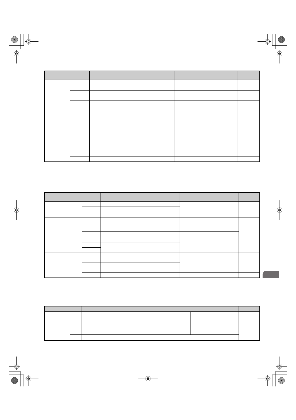
Output Terminals
lists the output terminals on the regenerative unit. Text in parenthesis indicates the default setting for each
multi-function output.
Table 3.6 Control Circuit Output Terminals
■
Serial Communication Terminals
Table 3.7 Control Circuit Terminals: Serial Communications
Analog Inputs
+V
Analog reference input
10.5 Vdc (max allowable current 20 mA)
–
-V
Analog reference input
-10.5 Vdc (max allowable current 20 mA)
–
A1
Multi-function analog input 1 (Reserved)
-10 to 10 Vdc, 0 to 10 Vdc
(input impedance: 20 k
Ω)
A2
Multi-function analog input 2 (Reserved)
• -10 to 10 Vdc, 0 to 10 Vdc
(input impedance: 20 k
Ω)
• 4 to 20 mA, 0 to 20 mA
(input impedance: 250
Ω)
• Voltage or current input must be
selected by DIP switch S1 and H3-09.
A3
Multi-function analog input 3 (Reserved)
• -10 to 10 Vdc, 0 to 10 Vdc
(input impedance: 20 k
Ω)
• Use DIP switch S4 on the terminal
board to select between analog and PTC
input.
AC
Frequency reference common
0 V
–
E (G)
Ground for shielded lines and option cards
–
–
Type
<1> Refrain from assigning functions to digital relay outputs that involve frequent switching, as doing so may shorten relay performance life.
Switching life is estimated at 200,000 times (assumes 1 A, resistive load).
No.
Terminal Name (Function)
Function (Signal Level)
Default Setting
Page
Fault Relay Output
MA
N.O. output (Fault)
30 Vdc, 10 mA to 1 A; 250 Vac,
10 mA to 1 A
Minimum load: 5 Vdc, 10 mA
MB
N.C. output (Fault)
MC
Fault output common
Multi-Function Relay
Output
M1
Multi-function relay output (During MC on)
30 Vdc, 10 mA to 1 A; 250 Vac,
10 mA to 1 A
Minimum load: 5 Vdc, 10 mA
M2
M3
Multi-function relay output (Operation Ready)
30 Vdc, 10 mA to 1 A; 250 Vac,
10 mA to 1 A
Minimum load: 5 Vdc, 10 mA
M4
M5
Multi-function relay output (During Run 1)
M6
Monitor Output
FM
Analog monitor output 1 (Power Supply Side
Power)
-10 to +10 Vdc, or 0 to +10 Vdc
AM
Analog monitor output 2 (Power Supply Side
Current)
AC
Monitor common
0 V
–
Type
No.
Signal Name
Function (Signal Level)
Page
MEMOBUS/
Modbus
Communication
<1> Enable the termination resistor in the last regenerative unit in a MEMOBUS/Modbus network by setting DIP switch S2 to the ON position.
R+
Communications input (+)
MEMOBUS/Modbus
communication: Use an
RS-422 or RS-485 cable to
connect the regenerative unit.
RS-422/RS-485
MEMOBUS/Modbus
communication protocol
115.2 kbps (maximum)
R-
Communications input (-)
S+
Communications output (+)
S-
Communications output (-)
IG
Shield ground
0 V
Type
No.
Terminal Name (Function)
Function (Signal Level)
Default Setting
Page
TOEP_C710656_08B_1_0.book 59 ページ 2015年2月5日 木曜日 午前10時7分