Alarm and error displays, Faults – Yaskawa R1000 Series Power Regenerative Unit User Manual
Page 88
5.2 Alarms, Faults, and Errors
88
YASKAWA ELECTRIC TOEP C710656 08B YASKAWA Power Regenerative Unit - R1000 Instruction Manual
◆ Alarm and Error Displays
■
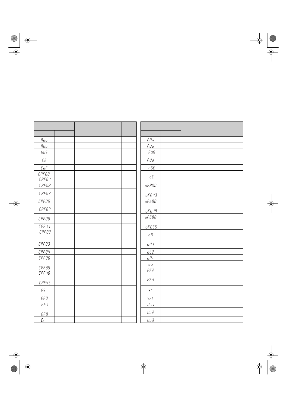
Faults
gives an overview of possible fault codes. Conditions such as overvoltages can trip faults and alarms. It is
important to distinguish between faults and alarms to determine the proper corrective actions. When the regenerative unit
detects a fault, the ALM indicator LED lights, the fault code appears on the digital operator, and the fault contact
MA-MB-MC triggers. An alarm is present if the ALM LED blinks and the fault code on the digital operator flashes. Refer
to
Minor Faults and Alarms on page 89
Table 5.2 Fault Displays
Digital Operator
Display
Name
Page
Digital Operator
Display
Name
Page
LED
LCD
LED
LCD
Aov
<1> Displayed as CPF00 when occurring at regenerative unit power up. When one of the faults occurs after successfully starting the regenerative
unit, the display will show CPF01. Displayed as CPF20 when occurring at regenerative unit power up. When one of the faults occurs after
successfully starting the regenerative unit, the display will show CPF21.
Power Supply Overvoltage
Fan
Internal Circulation Fan Fault
AUv
Power Supply Undervoltage
Fdv
Power Supply Frequency Fault
bUS
Option Communication Error
FUA
AC Fuse Blowout
CE
MEMOBUS/Modbus
Communication Error
FUd
DC Fuse Blowout
CoF
Current Offset Fault
nSE
Node Setup Error
,
CPF00,
CPF01
Control Circuit Error
oC
Overcurrent
CPF02
A/D Conversion Error
to
oFA00 to
oFA43
Option Card Fault (CN5-A)
CPF03
Control Board Connection
Error
CPF06
EEPROM Memory Data Error
to
oFb00 to
oFb17
Option Card Fault (CN5-B)
CPF07
Terminal Board Connection
Error
CPF08
Terminal Board Connection
Error
to
oFC00 to
oFC55
Option Card Fault (CN5-C)
,
CPF11 to
CPF22
Control Circuit Error
oH
Heatsink Overheat
CPF23
Control Board Connection
Error
oH1
Overheat 1
CPF24
Unit Capacity Detect Fault
oL2
Overload
to
,
to
CPF26 to
CPF35,
CPF40 to
CPF45
Control Circuit Error
oPr
Operator Connection Fault
ov
Overvoltage
PF2
Input Power Supply Fault
PF3
Input Phase Loss Detection
E5
MECHATROLINK
Watchdog Timer Error
SC
IGBT Short Circuit or Ground
Fault
EF0
Option Card External Fault
SrC
Phase Order Fault
to
EF1
to
EF8
External Fault
(input terminal S1 to S8)
Uv1
Main Circuit Undervoltage
Uv2
Control Power Supply
Undervoltage
Err
EEPROM Write Error
Uv3
Soft Charge Circuit Fault
TOEP_C710656_08B_1_0.book 88 ページ 2015年2月5日 木曜日 午前10時7分