Yaskawa R1000 Series Power Regenerative Unit User Manual
Page 160
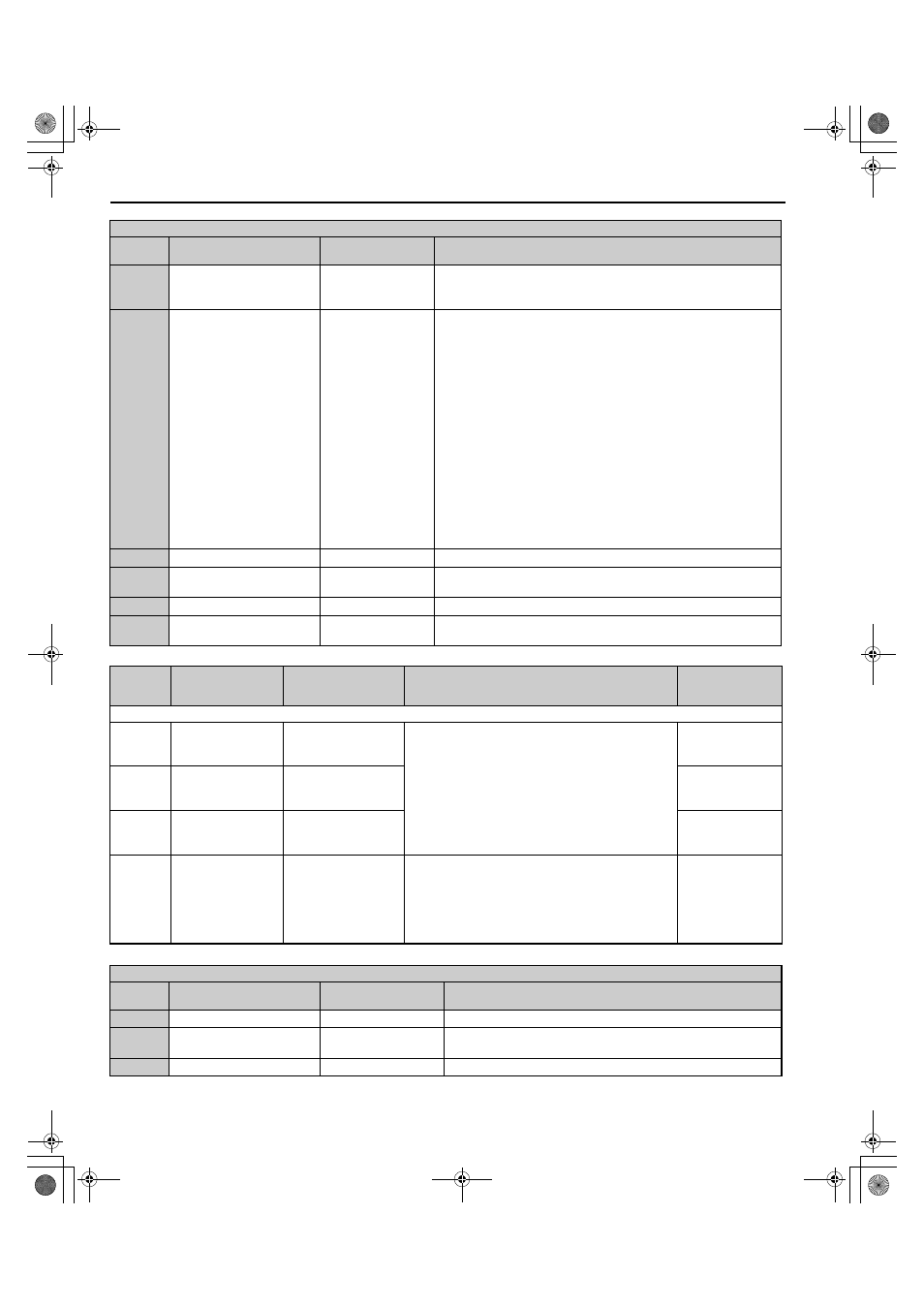
B.2 Parameter Tables
160
YASKAWA ELECTRIC TOEP C710656 08B YASKAWA Power Regenerative Unit - R1000 Instruction Manual
1B
Program lockout
Program Lockout
Open: Parameters cannot be edited (except for U1-01 if the reference
source is assigned to the digital operator).
Closed: Parameters can be edited and saved.
24 to 27
2C to 2F
External fault
External fault
24: NO/ Always Det,
Coast to Stop
25: NC/Always Det,
Coast to Stop
26: NO/During RUN,
Coast to Stop
27: NC/During RUN,
Coast to Stop
2C: NO/Always Det,
Alarm Only
2D: NC/Always Det,
Alarm Only
2E: NO/ During RUN,
Alarm Only
2F: NC/During RUN,
Alarm Only
24: N.O., Always detected, coast to stop
25: N.C., Always detected, coast to stop
26: N.O., During run, coast to stop
27: N.C., During run, coast to stop
2C: N.O., Always detected, alarm only (continue running)
2D: N.C., Always detected, alarm only (continue running)
2E: N.O., During run, alarm only (continue running)
2F: N.C., During run, alarm only (continue running)
3C
Forced Operation Command
Manual Run
Closed: Starts the operation of the regenerative unit.
3D
Automatic Operation
Command
Auto Run
Closed: The regenerative unit starts to operate when the voltage of the bus
increases (i.e., when a regenerative state is reached).
47
Node Setup
Node SetUp
Closed: Node setup for SI-S3 enabled.
67
Communications test mode
Comm Test Mode
Tests the MEMOBUS/Modbus RS-422/RS-485 interface. Displays
“PASS” if the test completes successfully.
No.
(Address
Hex)
Name
LCD Display
Description
Values
H2: Multi-Function Relay Outputs
H2-01
(40BH)
Terminal M1-M2
function selection
(relay)
M1-M2 Func Sel
Refer to
H2 Multi-Function Relay Output Settings on
for a description of setting values.
Note: Set unused terminals to F.
Default: 26
Min.: 0
Max.: 160
H2-02
(40CH)
Terminal M3-M4
Function Selection
(Relay)
P1/PC Func Sel
Default: 6
Min.: 0
Max.: 160
H2-03
(40DH)
Terminal M5-M6
Function Selection
(Relay)
P2/PC Func Sel
Default: 25
Min.: 0
Max.: 160
H2-06
(437H)
kWh Monitor Pulse
Output Unit Selection
Pwr Mon Unit Sel
1: 1 kWh units
2: 10 kWh units
3: 100 kWh units
4: 1000 kWh units
Select the output unit of the multi-function contact when
H2-01 to H2-03 is set to 3A.
1: 1 kWh
2: 10 kWh
3: 100 kWh
4: 1000 kWh
Default: 1
Min.: 1
Max.: 4
H2 Multi-Function Relay Output Settings
H2-
Setting
Function
LCD Display
Description
0
During run
During RUN 1
Closed: A Run command is active or voltage is output.
6
Operation Ready
Drive Ready
Closed: Power up is complete and the regenerative unit is ready to accept
a Run command.
7
DC bus undervoltage
DC Bus Undervolt
Closed: DC bus voltage is below the Uv trip level set in L2-05.
H1 Multi-Function Digital Input Selections
H1-
Setting
Function
LCD Display
Description
TOEP_C710656_08B_1_0.book 160 ページ 2015年2月5日 木曜日 午前10時7分