Yaskawa R1000 Series Power Regenerative Unit User Manual
Page 171
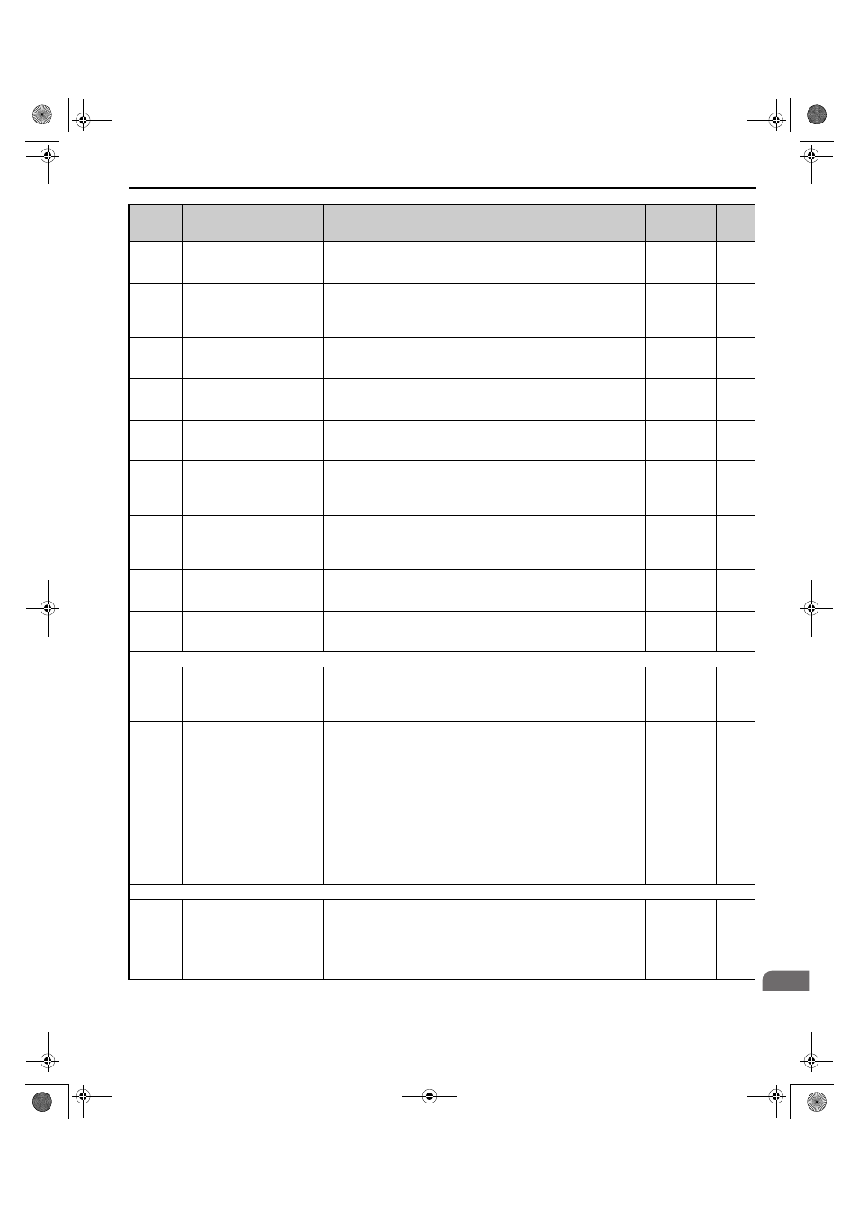
B.2 Parameter Tables
YASKAWA ELECTRIC TOEP C710656 08B YASKAWA Power Regenerative Unit - R1000 Instruction Manual
171
B
U2-58
(847H)
Power Supply
Frequency at
Previous Fault
AC
Frequency
Shows the frequency on the power supply side.
No signal
output
available
0.1 Hz
U2-59
(848H)
Power Supply
Side Current
Reference at
Previous Fault
AC Current
Ref
Shows the current reference on the power supply side when the most
recent fault occurred.
No signal
output
available
1 A
U2-60
(849H)
Power Factor at
Previous Fault
Power
Factor
Shows the power factor when the most recent fault occurred.
No signal
output
available
1%
U2-61
(84AH)
Active Current
Reference at
Previous Fault
Active
Current
Shows the active current when the most recent fault occurred.
No signal
output
available
0.1%
U2-62
(84BH)
Reactive Current
Reference at
Previous Fault
Reactive
Current
Shows the reactive current when the most recent fault occurred.
No signal
output
available
0.1%
U2-63
(84CH)
DC Bus Voltage
Reference at
Previous Fault
(After SFS)
DC V SFS
Level
Shows the DC bus voltage reference after the soft starter.
No signal
output
available
1 V
U2-64
(84DH)
Avr Input
(Voltage
Deviation) at
Previous Fault
AVR Input Shows the Avr input.
No signal
output
available
1 V
U2-65
(84EH)
Control Voltage
Reference (Vq) at
Previous Fault
Voltage Ref
(Vq)
Shows the control voltage reference (Vq) when the most recent fault
occurred.
No signal
output
available
1 V
U2-66
(84FH)
Control Voltage
Reference (Vd) at
Previous Fault
Voltage Ref
(Vd)
Shows the control voltage reference (Vd) when the most recent fault
occurred.
No signal
output
available
1 V
U3: Fault History
U3-01 to
U3-04
(90H to
93H)
First to 4th Most
Recent Fault
Fault
Message
Displays the first to the fourth most recent faults.
No signal
output
available
–
U3-05 to
U3-10
(804H to
809H)
5th to 10th Most
Recent Fault
Fault
Message
Displays the fifth to the tenth most recent faults.
After ten faults, data for the oldest fault is deleted. The most recent fault
appears in U3-01, with the next most recent fault appearing in U3-02. The
data is moved to the next monitor parameter each time a fault occurs.
No signal
output
available
–
U3-11 to
U3-14
(94H to
97H)
Cumulative
Operation Time at
1st to 4th Most
Recent Fault
Elapsed
Time
Displays the cumulative operation time when the first to the fourth most
recent faults occurred.
No signal
output
available
1 h
U3-15 to
U3-20
(80EH to
813H)
Cumulative
Operation Time at
5th to 10th Most
Recent Fault
Elapsed
Time
Displays the cumulative operation time when the fifth to the tenth most
recent faults occurred.
No signal
output
available
1 h
U4: Maintenance Monitors
U4-01
(4CH)
Cumulative
Operation Time
Drv
Elapsed
Time
Displays the cumulative operation time of the regenerative unit. The value
for the cumulative operation time counter can be reset in parameter o4-01.
Use parameter o4-02 to determine if the operation time should start as
soon as the power is switched on or only while the Run command is
present. The maximum number displayed is 99999, after which the value
is reset to 0.
No signal
output
available
1 h
No.
(Address
Hex)
Name
LCD
Display
Description
Analog
Output
Level
Unit
TOEP_C710656_08B_1_0.book 171 ページ 2015年2月5日 木曜日 午前10時7分