Aenc_rst> block fault conditions, Internal fault bit, Cause – Yaskawa MP2000 User Manual
Page 119: Note, Aenc_rst> working registers, Register no, Type, Name, Description, Register no. type name description
TECHNICAL NOTE
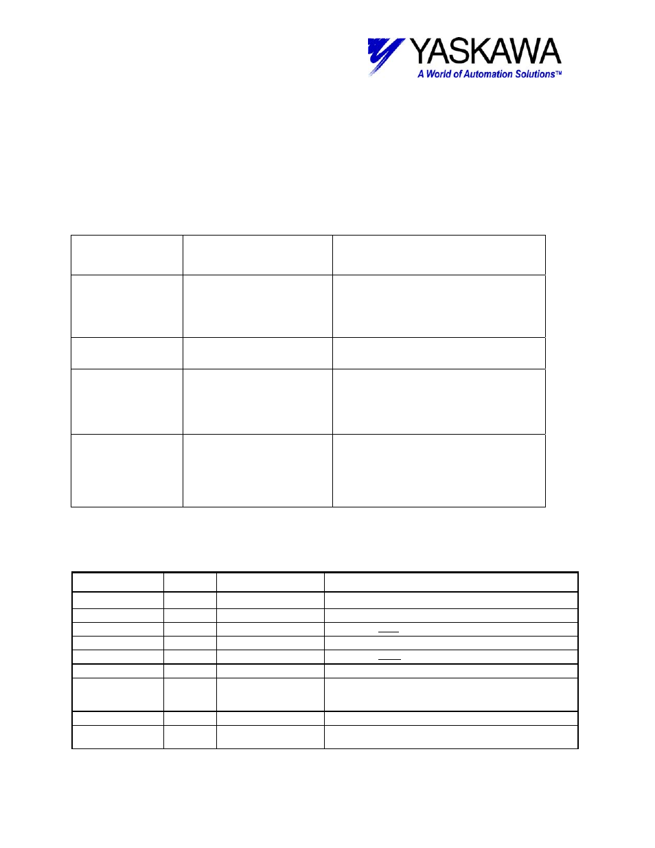
<AENC_RST> Block Fault Conditions:
The following table outlines several situations that may cause an error, and will turn on
the blocks “Error” output bit. The block “Error” output will cleared if the EXECUTE bit
goes low, but the Error ID (MW***81) will remain in the RDA. To reset the Error ID, use
the Alarm Reset Function Block.
Note that each axis has its own Error ID stored in its RDA axis section, offset by 300 for
each axis. Example: Axis#1 stores to MW30181, Axis #2 stores to MW30481, etc.
Internal Fault
Bit
Cause Note
TimeOut_Error
AB000010
Absolute encoder rest
operation does not complete
within 5 seconds
It is possible there is no absolute encoder. It is a
Sigma I (SGD-xxxN or SGDB-xxxN) Mechatrolink I
system, and the operation can not be done. The
operation already occurred and can not happen a
second time, with out a power cycle (Sigma II) or
some motion (SigmaIII)
RDA_Range_Error
AB000012
Axis number is out of range.
CmdCode_Error
AB000014
Motion Command Code
(MCC) was other than Zero
(NOP) when EXECUTE
transitioned from OFF ->
ON.
This is determined by monitoring the Motion
Command Code response register (IWxx08) for
Zero.
Svon_Error
AB000015
If was ON when EXECUTE
transitioned from OFF ->
ON.
This side effect of this operation is loss of
Mechatrolink II synchronization. Synchronization is
restablished by the function block after it commands
an Alarm Reset. If Servo was ON, it would be turned
OFF as due to the loss of synchronization. It is
better that the Servo is off before the operation
begins.
<AENC_RST> Working Registers
This table outlines the data in the five registers used by the function block. There is not usually any need
for the user to access any of these bits directly.
Register No.
Type
Name
Description
AW00000
WORKING_REG0
Bit
0
IN
EXECUTE_TRUE
EXECUTE
input (XB000000)
Bit
1
IN
EXECUTE_1stPASS
One shot on rising edge of Execute input to set axis data.
Bit
2
Working Operate
Start operation
Bit
3
Working EXECUTE_TRANS_OFF One shot on falling edge of Execute input to set axis data.
Bit
4
Working InRDA_Range
Goes high for one scan if “AXIS” input is in range.
Bit
5
Working MCC_RESP_ABS_RST
Goes High when Motion Command Code (MCC) Response
Register (IWxx08) is equal to 22, “ABS_RST” operation has
happened
Bit
6
Working Send_ABS_RST_MCC
Goes High when it is time to send MCC 22 “ABS_RST”
Bit
7
Working MCC_RESPONCE_NOP
Goes High when Motion Command Code (MCC) Response
Register (IWxx08) is equal to 0, “NOP” (No Operation) is true
File: MP2000_IndividualFunctionDocument_RevC 119/168
Doc Number: eng.MCD.05.101
11/17/2005