Chngdyn> input and output register map – Yaskawa MP2000 User Manual
Page 31
TECHNICAL NOTE
File: MP2000_IndividualFunctionDocument_RevC 31/168
Doc Number:
EF.MCD.05.101
11/17/2005
• Five words are used as working registers for this function, starting at the address
in Data05W.
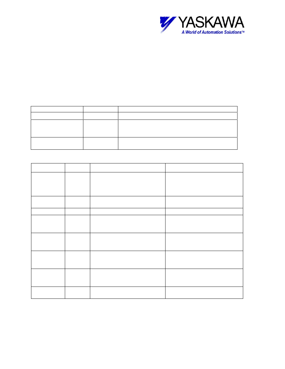
<CHNGDYN> Input and Output Register Map
Output Registers
The following registers are used as outputs from the function block. They can be
monitored by the LadderWorks program to check the execution of the function.
OUTPUT TYPE
DESCRIPTION
RUNNING
BIT
THE FUNCTION BLOCK EXECUTES (*O) IN.
DONE
BIT
THERE ARE NEITHER EXECUTION
COMPLETION (ALL THE VALUES ARE SET)
NOR ERROR GENERATION.
ERROR
BIT
ERROR GENERATION (THE INPUT VALUE IS
OUTSIDE A SET RANGE)
Input Registers
Input
Type
Description
Range and state
EXECUTE
Bit
Block enable – see block
operation notes.
Rising edge initiates block
TRUE – continue executing
FALSE – see block operation
notes
AXIS
Word
Axis number related to the
block.
1~16
TIME
Word
Timer setting
1~32767[sec]
SCURVE
Long
S-Curve value to store in RDA
and controller
Zero to Max value is limited to
max value in RDA (ML3**34).
Value is stored in milliseconds
ACCEL
Long
Acceleration value to store in
RDA and controller.
Zero to Max value is limited to
max value in RDA (ML3**22).
Value is stored in counts/sec
2
DECEL
Long
Deceleration value to store in
RDA and controller.
Zero to Max value is limited to
max value in RDA (ML3**28).
Value is stored in counts/sec
2
SPEED
Long
Velocity value to store in RDA
and controller.
Max absolute value is limited to
max value in RDA (ML3**28).
Value is stored in counts/sec.
DATA05W
Address Address of the first working
register.
Five words of register space are
used by this function.