Rdainit2> input and output register map – Yaskawa MP2000 User Manual
Page 133
TECHNICAL NOTE
<RDAINIT2> Input and Output Register Map
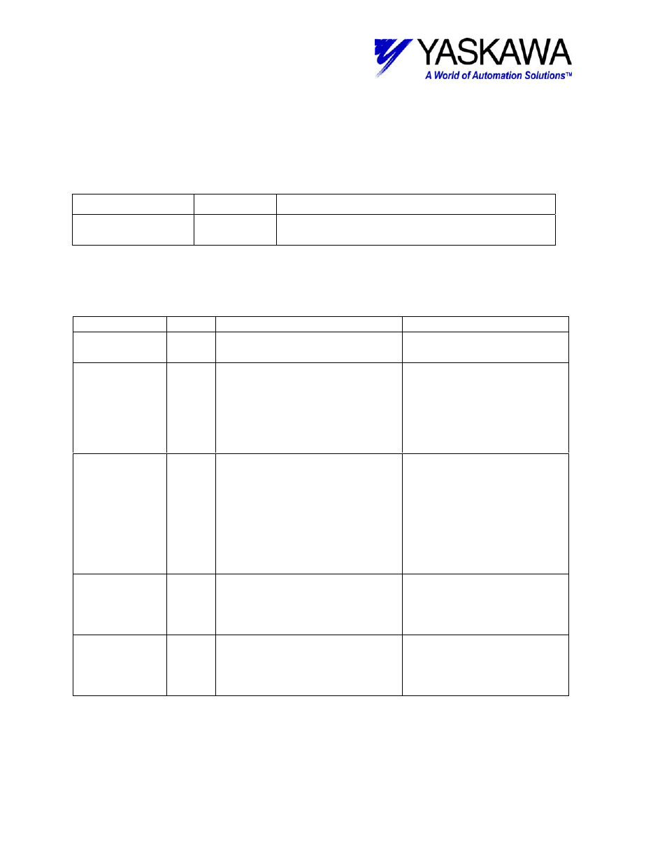
Output Registers
The following registers are used as outputs from the function block. They can be
monitored by the LadderWorks program to check the execution of the function.
Output TYPE
Content
RUNNING
Bit
Goes high while block is updating RDA,
Updating completes in one scan.
Input Registers
The following registers are used as inputs to the function block. They select the options
and define the parameters that the user needs to make the function work as necessary.
Input
Type
Description
Range and state
AXISRDA
Word Logical axis number related to
the block
1 to 16
MODULE
Word Module address given to
SVA-01 or SVB. This is same
as ‘Circuit Number’ defined in
module configuration. This
links to the AXISRDA which is
used in all motion blocks.
1 to 16
AXIS-NUM
Word Axis number axis is plugged
into on SVA-01 or SVB
module. This is same as
“Axis Number” within the
defined “Circuit Number’.
This links to the AXISRDA
which is used in all motion
blocks.
1to 2 (SVA-01 module)
1 to 16 (SVB-01 module)
MTRSPD
Word Rated speed of motor on axis
on RPM. This is necessary
for calculating accels and
decals.
1 to 32767
RESOLUTN
Long Resolution of motors encoder
(post-quad). This is
necessary to convert units for
counts and revs.
1 to 2147483647.
File: MP2000_IndividualFunctionDocument_RevC 133/168
Doc Number: eng.MCD.05.101
11/17/2005