Yaskawa MP900 Series Ladder Programming Manual User Manual
Page 18
1.2 Features of Ladder Programming for MP2000-series Machine Controllers
1.2.1 Types of Ladder Drawings and Their Different Execution Timing
1-3
Introduction to Ladder Programming
1
1.2 Features of Ladder Programming for MP2000-series Machine
Controllers
This section describes the features of ladder programming.
1.2.1 Types of Ladder Drawings and Their Different Execution Timing
Ladder programs are managed in units of drawings (DWG). These are called ladder drawings.
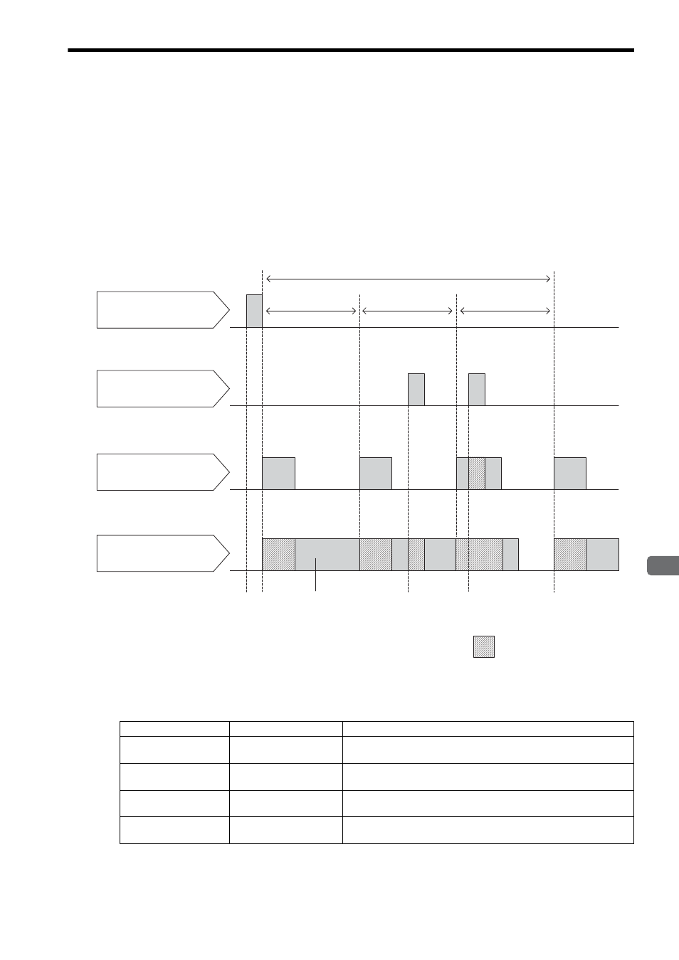
In the MP2000-series Machine Controllers, ladder drawings are executed at various times, as illustrated in the follow-
ing figure.
Processing can be executed at the appropriate time by programming it in the appropriate ladder drawing.
Drawing Execution Timing
The drawings with lower numbers have higher execution priority.
Interrupt
signal
Power ON
High-speed
scan cycle
Low-speed scan cycle
Processed during
idle time of the
high-speed scan.
High-speed
scan cycle
High-speed
scan cycle
Interrupt signal
DWG.A
→ Executed only when power
is turned ON.
DWG.H
→ Executed in the high-speed
scan cycle.
DWG.L
→ Executed in the low-speed
scan cycle.
DWG.I
→ Executed only when an
interrupt signal is detected.
On standby while
drawings of higher
priority are processed.
:
Priority
Ladder Drawing
Execution Timing (Processing Example)
1 (High)
DWG.A
This drawing is executed only once when the power supply is turned ON
(e.g., for data initialization).
2 ( )
DWG.I
This drawing is executed when an interrupt signal is detected (e.g., for
interrupt processing for external signals).
3 ( )
DWG.H
This drawing is executed every high-speed scan cycle (e.g., for motion
control).
4 (Low)
DWG.L
This drawing is executed every low-speed scan cycle (e.g., for touch
panel display processing).
↓
↓