Yaskawa MP900 Series Ladder Programming Manual User Manual
Page 221
5.8 DDC Instructions
5.8.5 PD Control (PD)
5-152
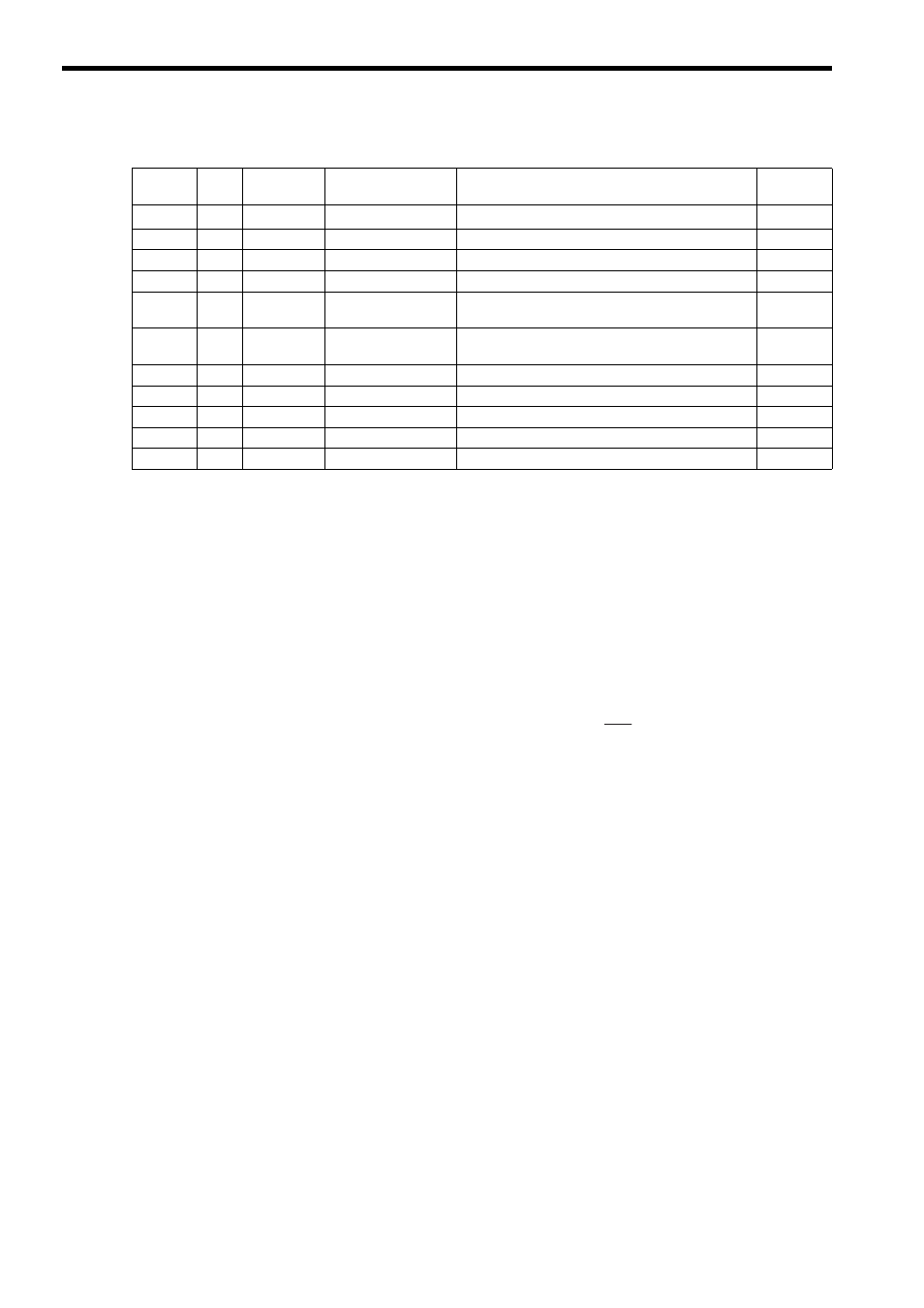
[ b ] Parameter Table Configuration for PD Instruction with Real Numbers
∗ The relay input and output bit assignments are the same as for integers.
[ c ] Internal Operation of the Instruction
The deviation X input is used to calculate the PD compensation output as shown below.
In the formula shown below, X’ is the previous input value of X, Ts is the scan time set value, and Td* is the differen-
tial time.
∗ The differential time (Td) is Td1 when X – X’ and X’ have the same sign, and Td2 when X – X’ and X’ have dif-
ferent signs.
P compensation = Upper/lower limit (UL or LL) of (Kp
× X)
D compensation = Kd
× (X
–
X’)
× Upper/lower limit (IUL or ILL) of
PD compensation = Upper/lower limit (UL or LL) of (P compensation + D compensation) and Dead zone A
(Width DB)
Address
Data
Type
Symbol
Name
Specification
I/O
0
W
RLY
Relay I/O
Relay inputs and relay outputs
*
IN/OUT
1
W
–
(Reserved.)
Spare register
–
2
F
Kp
P gain
Gain for the P compensation
IN
4
F
Kd
D gain
Gain for the input to the differential circuit
IN
6
F
Td1
Differential time for
divergence
Differential time used when the input diverges (s)
IN
8
F
Td2
Differential time for
convergence
Differential time used when the input converges (s)
IN
10
F
UL
PD upper limit
Upper limit for the P + D compensation
IN
12
F
LL
PD lower limit
Lower limit for the P + D compensation
IN
14
F
DB
PD output dead zone
Dead zone width for the P + D compensation
IN
16
F
Y
PD output
PD compensation output (output to Out)
OUT
18
F
X
Input value storage
Storage of current input value
OUT
Td
Ts