2 ) format – Yaskawa MP900 Series Ladder Programming Manual User Manual
Page 345
5.10 System Function Instructions
5.10.11 Write Motion Register (MOTREG-W)
5-276
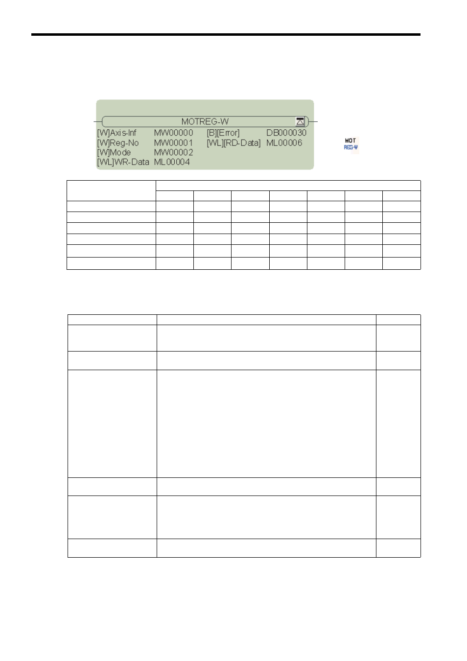
( 2 ) Format
∗ C and # registers cannot be used. These parameters may be omitted.
The parameters are described in the following table.
Parameter Name
Applicable Data Types
B
W
L
F
A
Index
Constant
Axis information (Axis-Inf)
×
{
×
×
×
×
×
Register address (Reg-No)
×
{
×
×
×
×
×
Mode
×
{
×
×
×
×
×
Write data (WR-Data)
×
{
{
×
×
×
×
Error
{
*
×
×
×
×
×
×
Read data (RD-Data)
×
{
*
{
*
×
×
×
×
Parameter Name
Description
I/O
Axis information (Axis-Inf)
Circuit number and axis number
Upper byte: Circuit number (01 to 10 hex)
Lower byte: Axis number (01 to 10 hex)
IN
Register address (Reg-No)
Integer register: 0000 to 007F hex
Double-length integer register: 0000 to 007E hex
IN
Mode
Access type and access size
Upper byte: Access type
0: Write WR-Data to specified register.
1: Write inclusive OR of specified register and WR-Data to specified
register.
2: Write AND of specified register and WR-Data to specified register.
Others: Write WR-Data to specified register.
Lower byte: Access size
0: Integer data
1: Double-length integer data
Others: Integer data
IN
Write data (WR-Data)
If the access size for Mode is an integer and the input data type is a double-
length integer, only the lower word will be used.
IN
Error
Error cause (Turns ON when an error occurs.)
The register cannot be written to or read from because the circuit number, axis
number, or register address is outside of the valid range, or because the Module
does not exist.
When an error occurs, RD-Data is set to 0.
OUT
Read data (RD-Data)
This is the data that is read after writing is completed.
If integer data is specified, the data is output with the sign.
OUT
Icon:
Key entry: MOTREG-W