2 ) format – Yaskawa MP900 Series Ladder Programming Manual User Manual
Page 234
5.8 DDC Instructions
5.8.8 Phase Lead Lag (LLAG)
5-165
Instructions
5
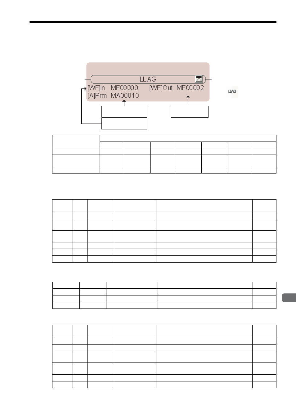
( 2 ) Format
∗ C and # registers cannot be used.
[ a ] Parameter Table Configuration for LLAG Instruction with Integers
∗ The relay input and output bits are assigned as given below. (Close = Bit change to 1 (ON), Open = Bit change to 0
(OFF))
[ b ] Parameter Table Configuration for LLAG Instruction with Real Numbers
∗ The relay input and output bit assignments are the same as for integers.
Parameter Name
Applicable Data Types
B
W
L
F
A
Index
Constant
Input value (In)
×
{
×
{
×
{
{
First address of
parameter table (Prm)
×
×
×
×
{
*
{
{
Output value (Out)
×
{
*
×
{
*
×
{
×
First address of
parameter table
Output value
Input value
Icon:
Key entry: LLAG
Address
Data
Type
Symbol
Name
Specification
I/O
0
W
RLY
Relay I/O
Relay inputs and relay outputs
*
IN/OUT
1
W
T2
Phase lead time con-
stant
Phase lead time constant (ms)
IN
2
W
T1
Phase lag time con-
stant
Phase lag time constant (ms)
IN
3
W
Y
LLAG output
LLAG output (output to Out)
OUT
4
W
REM
Remainder
Remainder storage
OUT
5
W
X
Input value storage
Input value storage
OUT
Bit
Symbol
Name
Specification
I/O
0
IRST
LLAG reset bit
This input is closed to reset the LLAG operation.
IN
1 to 7
–
(Reserved.)
Spare input relays
IN
8 to F
–
(Reserved.)
Spare output relays
OUT
Address
Data
Type
Symbol
Name
Specification
I/O
0
W
RLY
Relay I/O
Relay inputs and relay outputs
*
IN/OUT
1
W
–
(Reserved.)
Spare register
–
2
F
T2
Phase lead time con-
stant
Phase lead time constant (s)
IN
4
F
T1
Phase lag time con-
stant
Phase lag time constant (s)
IN
6
F
Y
LLAG output
LLAG output (output to Out)
OUT
8
F
X
Input value storage
Input value storage
OUT