Yaskawa MP900 Series Ladder Programming Manual User Manual
Page 216
5.8 DDC Instructions
5.8.4 PI Control (PI)
5-147
Instructions
5
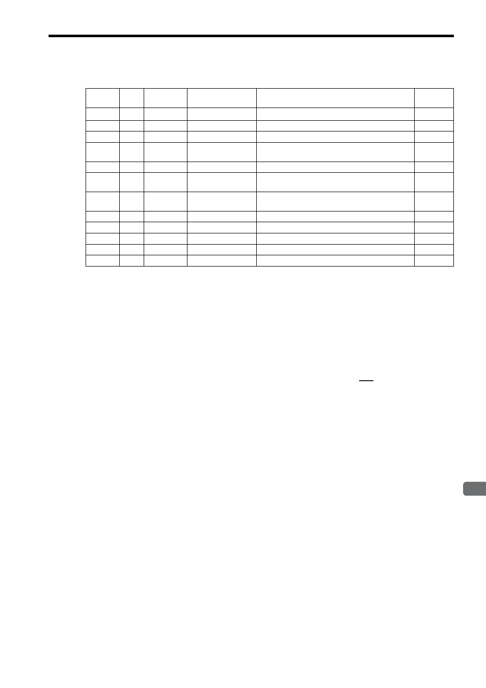
[ b ] Parameter Table Configuration for PI Instruction with Real Numbers
∗ The relay input and output bit assignments are the same as for integers.
[ c ] Internal Operation of the Instruction
The deviation X input is used to calculate the output value (PI compensation) as shown below.
In the formula shown below, Yi’ is the previous I compensation of Yi and Ts is the scan time set value.
When IRST (reset integration) is closed, the PI compensation is calculated with the I compensation set to 0.
P compensation = Upper/lower limit (UL or LL) of (Kp
× X)
Yi (I compensation) = Upper/lower limit (IUL or ILL) of { (Ki
× X + IREM) /
+ Yi’}
Y (PI compensation) = P compensation + Upper/lower limit (UL or LL) and Dead zone A (Width DB) of the I
compensation
Address
Data
Type
Symbol
Name
Specification
I/O
0
W
RLY
Relay I/O
Relay inputs and relay outputs
*
IN/OUT
1
W
–
(Reserved.)
Spare register
–
2
F
Kp
P gain
Gain for the P compensation
IN
4
F
Ki
Integral adjustment
gain
Gain for the input to the integral circuit
IN
6
F
Ti
Integral time
Integral time (s)
IN
8
F
IUL
Upper integration
limit
Upper limit for the I compensation
IN
10
F
ILL
Lower integration
limit
Lower limit for the I compensation
IN
12
F
UL
PI upper limit
Upper limit for the P + I compensation
IN
14
F
LL
PI lower limit
Lower limit for the P + I compensation
IN
16
F
DB
PI output dead zone
Dead zone width for the P + I compensation
IN
18
F
Y
PI output
PI compensation output (output to Out)
OUT
20
F
Yi
I compensation
I compensation storage
OUT
Ti
Ts