7 rising-edge pulses (on-pls), 1 ) operation, 2 ) format – Yaskawa MP900 Series Ladder Programming Manual User Manual
Page 84
5.2 Relay Circuit Instructions
5.2.7 Rising-edge Pulses (ON-PLS)
5-15
Instructions
5
5.2.7 Rising-edge Pulses (ON-PLS)
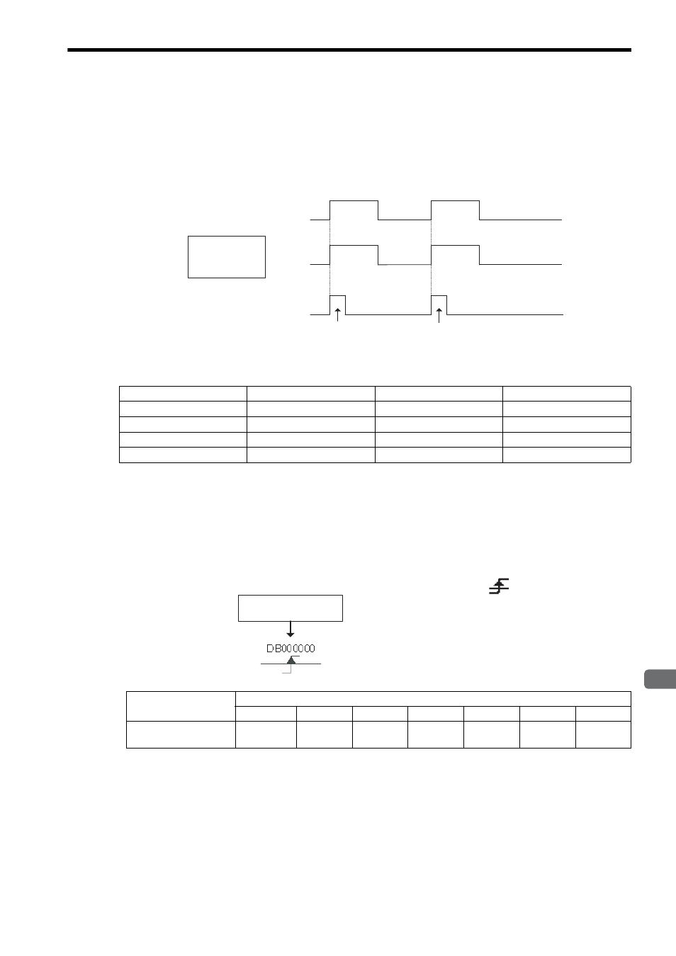
( 1 ) Operation
The ON-PLS instruction sets the bit output to 1 (ON) for only one scan when the bit input changes from 0 (OFF) to 1
(ON). The previous value of the bit input is saved in the Previous Value Register of the ON-PLS instruction.
The following table shows the relationship between the bit input of the ON-PLS instruction, the Previous Value Regis-
ter, and the bit output.
In the third row of the table, notice how the bit input changes from 0 (OFF) in the Previous Value Register to 1 (ON),
causing the ON-PLS instruction to set the bit output to 1 (ON).
( 2 ) Format
∗ C and # registers cannot be used.
The Previous Value Register holds the previous value of the bit input. Do not use other instructions to set the value
of this register.
Bit Input
Previous Value Register
ON-PLS Instruction
Bit Output
0 (OFF)
0 (OFF)
→
0 (OFF)
0 (OFF)
1 (ON)
→
0 (OFF)
1 (ON)
0 (OFF)
→
1 (ON)
1 (ON)
1 (ON)
→
0 (OFF)
Bit input
Bit output
1 (ON)
0 (OFF)
1 (ON)
0 (OFF)
Previous Value
Register
1 (ON)
0 (OFF)
1 scan
1 scan
Parameter Name
Applicable Data Types
B
W
L
F
A
Index
Constant
Previous Value
Register
{
*
×
×
×
×
×
×
Previous Value Register
Icon:
Key entry: ]P