13 pulse width modulation (pwm), 1 ) operation – Yaskawa MP900 Series Ladder Programming Manual User Manual
Page 263
5.8 DDC Instructions
5.8.13 Pulse Width Modulation (PWM)
5-194
5.8.13 Pulse Width Modulation (PWM)
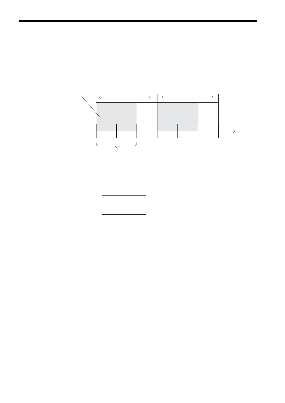
( 1 ) Operation
The PWM instruction converts the input value (from -100.00% to 100.00%) using pulse-width modulation and outputs
the result to the output value and parameter table. The input value and output value must be integers. Double-length
integers and real numbers cannot be used.
The ON output time and number of ON output scans of the PWM instruction can be calculated with the following for-
mula.
X is the input value, PWMT is the PWM cycle (ms), and Ts is the scan time set value (ms).
The relation between the input value and the PWM output ON ratio is as follows:
Input value 100.00%
→ 100% ON (ON output time = PWMT)
Input value 0.00%
→ 50% ON (ON output time = PWMT/2)
Input value -100.00%
→ 0% ON (ON output time = 0)
After turning ON the power supply, close PWMRST (PWM reset) to clear all internal calculations before using
the PWM instruction. When the PWM reset bit is closed, all internal calculations are reset and then the PMW
operation starts execution from that point.
1
(ON)
0
(OFF)
0
(OFF)
1
(ON)
PWMT (PWM cycle)
ON output time
(number of ON output scans)
Output value for
PWM instruction
Scan
PWMT (PWM cycle)
ON output time =
Number of ON output scans =
PWMT (X + 10,000)
20,000
PWMT (X + 10,000)
Ts × 20,000