3 ) programming example – Yaskawa MP900 Series Ladder Programming Manual User Manual
Page 265
Advertising
5.8 DDC Instructions
5.8.13 Pulse Width Modulation (PWM)
5-196
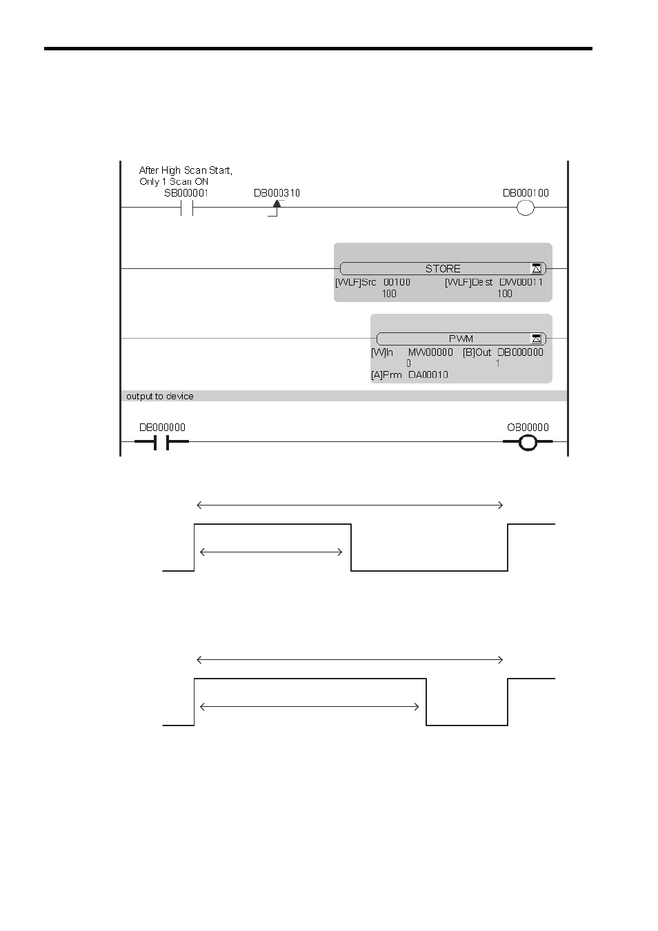
( 3 ) Programming Example
In the following programming example, the PWM output for the input value in MW00000 is stored in OB000000
where the PWM cycle is 100 ms.
This figure shows the output of OB000000 when MW00000 is 0 (0%: ON output time is 1/2 of the PWM cycle).
This figure shows the output of OB000000 when MW00000 is 7,500 (75%: ON output time is 3/4 of the PWM cycle).
PWM cycle = 100 ms
ON
OFF
ON output time = 50 ms
Number of ON output scans = 50 ms/scan time set value
ON
OFF
PWM cycle = 100 ms
ON output time = 75 ms
Number of ON output scans = 75 ms/scan time set value
Advertising
This manual is related to the following products: