Yaskawa MP900 Series Ladder Programming Manual User Manual
Page 248
5.8 DDC Instructions
5.8.11 Linear Accelerator/Decelerator 1 (LAU)
5-179
Instructions
5
[ b ] Parameter Table Configuration for LAU Instruction with Real Numbers
∗ The relay input and output bits are assigned as given below. (Close = Bit change to 1 (ON), Open = Bit change to 0
(OFF))
If QS (quick stop) is opened, QT (quick stop time) is used as the acceleration/deceleration time.
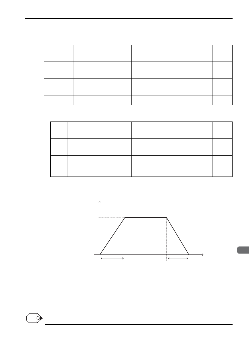
The acceleration time (AT) is the time from the 0% speed to the 100% speed. The deceleration time (BT) is the time
from the 100% speed to the 0% speed. The 100% speed is set as the 100% level of input. The setting of this parameter
determines the acceleration/deceleration rate. When the input speed is applied, operation is performed at the accelera-
tion/deceleration rate.
Therefore, the ratio between the set value for LV (input at 100% level) and the input speed determines the actual accel-
eration/deceleration time.
Refer to ( 4 ) Additional Information for details on the processing that is performed internally by the LAU instruction.
When QS (quick stop) opens (OFF), the acceleration/deceleration time is set to the QT (quick stop time).
To execute a quick stop, open (OFF) QS (quick stop) and set the input speed to 0 at the same time.
Address
Data
Type
Symbol
Name
Specification
I/O
0
W
RLY
Relay I/O
Relay inputs and relay outputs
*
IN/OUT
1
W
–
(Reserved.)
Spare register
–
2
F
LV
100% level of input
Scale for 100% input
IN
4
F
AT
Acceleration time
Time to accelerate from 0% to 100% (s)
IN
6
F
BT
Deceleration time
Time to decelerate from 100% to 0% (s)
IN
8
F
QT
Quick stop time
Time to make a quick stop from 100% to 0% (s)
IN
10
F
V
Current speed
LAU output (output to Out)
OUT
12
F
DVDT
Current acceleration/
deceleration rate
The current acceleration or deceleration rate is output.
OUT
Bit
Symbol
Name
Specification
I/O
0
RN
Line running
This input is closed to run the line.
IN
1
QS
Quick stop
This input is opened to execute a quick stop.
IN
2 to 7
–
(Reserved.)
Spare input relays
IN
8
ARY
Accelerating
This output is closed during acceleration.
OUT
9
BRY
Decelerating
This output is closed during deceleration.
OUT
A
LSP
Zero speed
This output is closed during zero speed.
OUT
B
EQU
Equal
This output is closed when the input speed equals the
output speed.
OUT
C to F
–
(Reserved.)
Spare output relays
OUT
Time (t)
Speed
BT
AT
Output Speed Waveform When Input Speed Is at the 100% Input Level (LV)
0%
Input speed at
100% input level
INFO