Resets, Resets -54 – Altera 40-Gbps Ethernet MAC and PHY MegaCore Function User Manual
Page 101
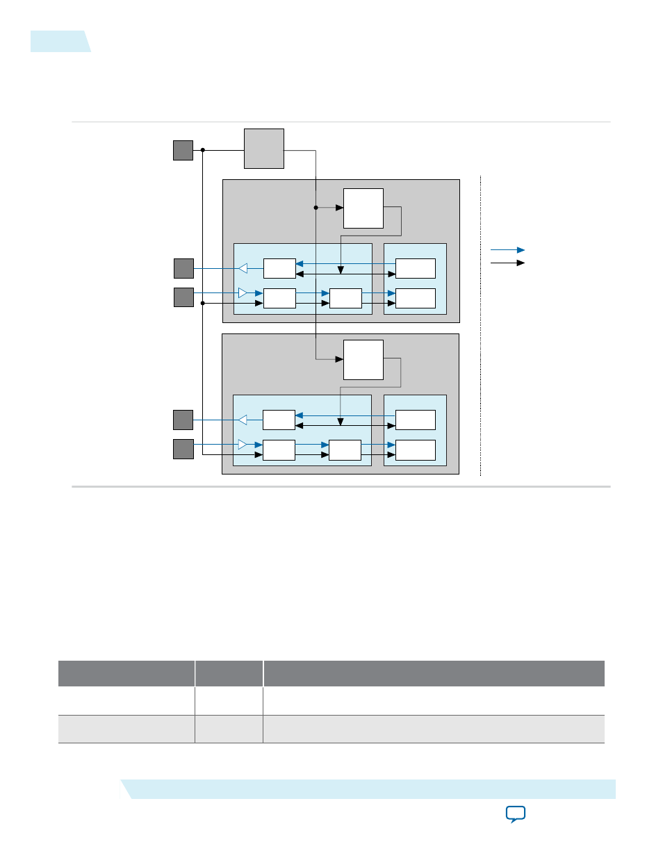
Figure 3-32: Clock Generation Circuitry
Provides a high-level view of the clock generation circuitry and clock distribution to the transceiver. In
Sync–E variations, distinct clocks drive the TX PLL (
tx_clk_ref
) and the CDR block (
rx_clk_ref
), and
the output clock from the CDR is brought out to the top level.
Transceiver
PMA
PCS
clk_ref
644.53125 or
322.265625
High
frequency
clock
FPGA-fabric
interface
Data
Clock
Tx PLL
Clock Gen
Buffer
(CGB)/2.5
Ser
Ser = Serializer
DeSer = DeSerializer
CDR
Tx PCS
Rx PCS
PMA
PCS
tx_serial
rx_serial
tx_serial
rx_serial
DeSer
Transceiver
PMA
PCS
Clock Gen
Buffer
(CGB)/2.5
Ser
CDR
Tx PCS
Rx PCS
PMA
PCS
DeSer
Parallel clock
257.8125 MHz
Parallel clock
257.8125 MHz
Resets
The 40-100GbE IP core provides the following two independent reset mechanisms:
• Asynchronous reset signals—A set of asynchronous reset signals you can assert to reset different parts
of the IP core. Use this method to initialize your IP core.
• Reset registers—A set of register bits you can write to reset different parts of the IP core. This method
is available for dynamic reset during operation.
Table 3-17: Asynchronous Reset Signals
The IP core provides five reset signals to allow independent reset control for all configurations. The MAC and
PHY asynchronous reset signals are included in the 40-100GbE IP Core with adapters and without adapters.
Signal Name
Direction
Description
mac_rx_arst_ST
Input
MAC RX asynchronous reset signal
mac_tx_arst_ST
Input
MAC TX asynchronous reset signal
3-54
Resets
UG-01088
2014.12.15
Altera Corporation
Functional Description