Test mode register, Test pattern counter register, Link fault signaling registers – Altera 40-Gbps Ethernet MAC and PHY MegaCore Function User Manual
Page 135
Test Mode Register
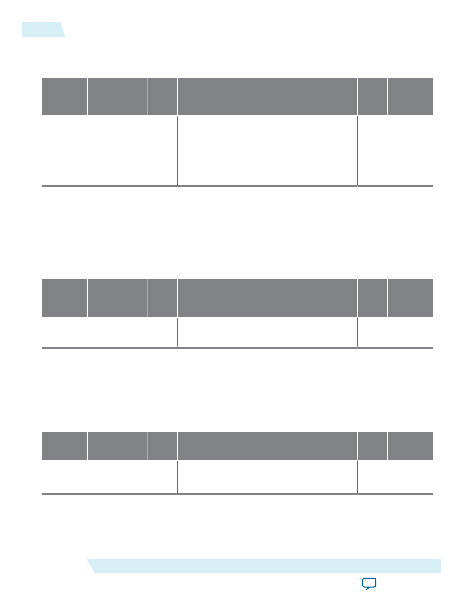
Table 3-32: Test Mode Register—Offset 0x019
Address
Name
Bit
Description
HW
Reset
Value
Access
0x019
TEST_MODE
[2]
This bit clears the test-pattern counter (
TEST_
PATTERN_COUNTER
register at offset 0x1A).
1’b0
RW
[1]
This bit enables RX test mode.
1’b0
RW
[0]
This bit enables TX test mode.
1’b0
RW
Related Information
PCS Test Pattern Generation and Test Pattern Check
Describes test pattern usage.
Test Pattern Counter Register
Table 3-33: Test Pattern Counter Register—Offset 0x1A
Unlike other statistics counters, the RX
TEST_PATTERN_COUNTER
is 32 bits and saturates.
Address
Name
Bit
Description
HW
Reset
Value
Access
0x1a
TEST_PATTERN_
COUNTER
[31:0] This register is the test pattern error counter. The
counter saturates at 0xffffffff.
32’b0
R
Related Information
PCS Test Pattern Generation and Test Pattern Check
Describes test pattern usage.
Link Fault Signaling Registers
Table 3-34: Link Fault Sequence Enable Register—Offset 0x01B
Address
Name
Bit
Description
HW
Value
Access
0x1b
Enable Link
Fault
Sequence
[0]
When asserted, the PCS generates remote fault
sequence if conditions are met.
1’b0
RW
3-88
Test Mode Register
UG-01088
2014.12.15
Altera Corporation
Functional Description