Task analysis, Figure 21 – H3C Technologies H3C Intelligent Management Center User Manual
Page 132
123
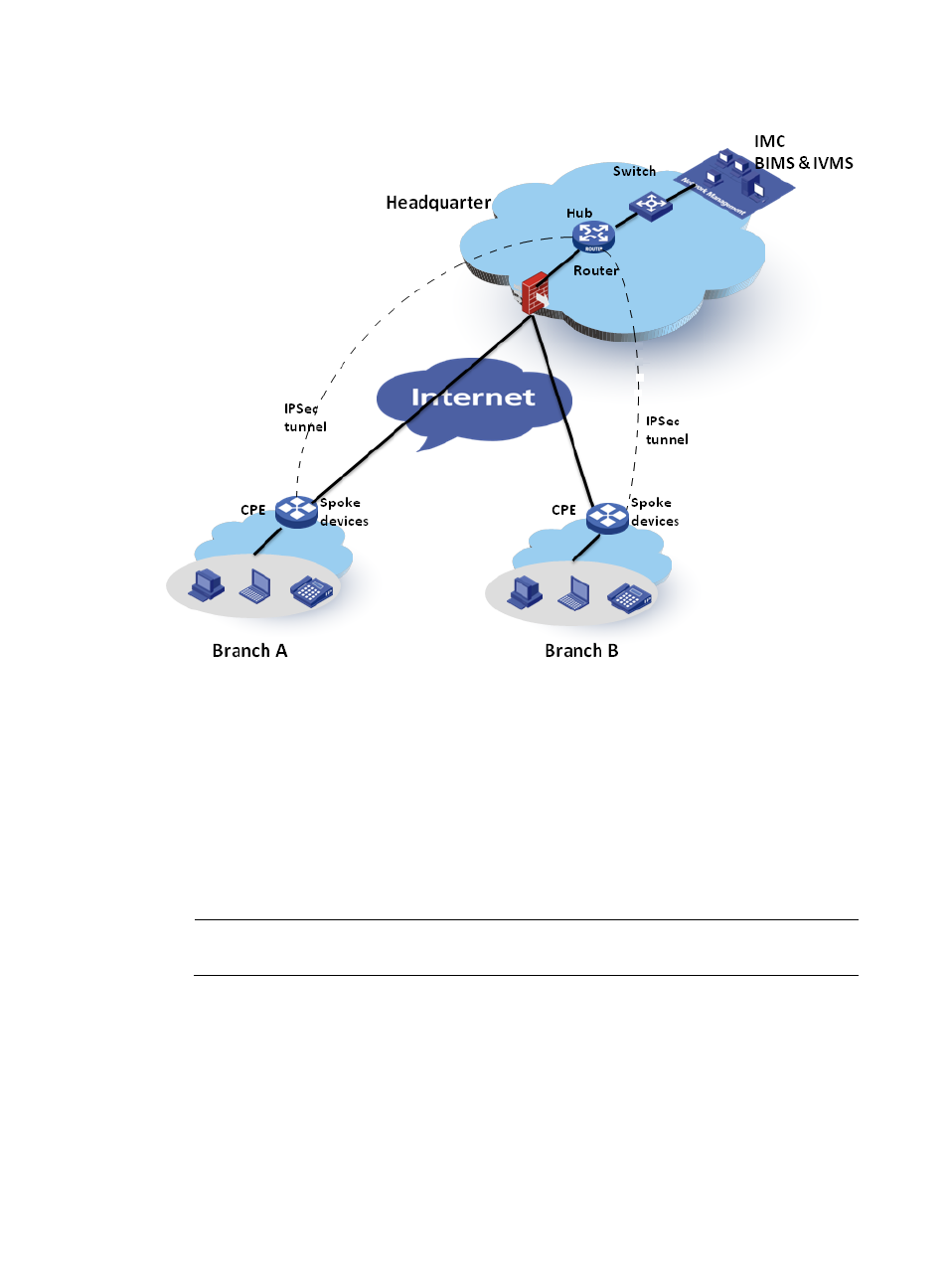
Figure 21 Network topology—Example 3
As network administrator, you want to enable IVMS to deploy its VPN tasks to CPEs managed by BIMS.
Task analysis
To use the cooperation schema of BIMS and IVMS in the above network (
), you can set the core
switch as the hub device, and the two CPEs, CPE A and CPE B, as spoke devices, and then create the
IPsec tunnel between the hub and spoke devices. The workflow is as follows:
1.
CPE A and CPE B access the Internet through ADSL and are assigned dynamic IP addresses.
2.
An operator adds CPE records for CPE A and CPE B in BIMS to create two virtual CPEs.
NOTE:
In this schema, you cannot use the BIMS zero-configuration solution.
3.
CPE A and CPE B boot and send connection requests to BIMS.
4.
BIMS authenticates the two CPEs. After the two CPEs pass the authentication, BIMS adds them as
real CPEs, which means the CPEs can be practically managed by BIMS. For more information, see
"
Example 3: Deploying CPEs in branch offices
."
5.
Through setting the device service parameters, IVMS is authorized to access BIMS device
information. It obtains information about BIMS devices using SOAP, and imports the BIMS
devices.
6.
An operator configures IPsec VPN parameters in IVMS, such as network domain.