Ection, Ally, Ights – NewTek TriCaster 8000 User Manual
Page 51: 1 connection details
Page | 35
Note: A mismatch of output format and connection type is possible at times. For
example, a Graphics player can display imagery that does not correspond to the current
output resolution or is not supported by the selected connection type. TriCaster will
attempt to display the output despite mismatches, but may not always succeed.
SECTION 3.9 TALLY LIGHTS
TriCaster’s Tally Light support allows you to connect external tally
lights and similar devices. These typically provide a red LED for the
video input that is currently selected on the Switcher’s Program row.
(Not a TriCaster Mini feature.)
Note: Tally over SDI, as supported by devices from Blackmagic Design, is natively
suported, and requires no special configuration. Please see also: Section 22.9 regrading
GPI support to trigger tally (and more); or search among third party tally solutions listed at
http://www.newtek.com/solutions/newtek-developer-network/all-partner-list.
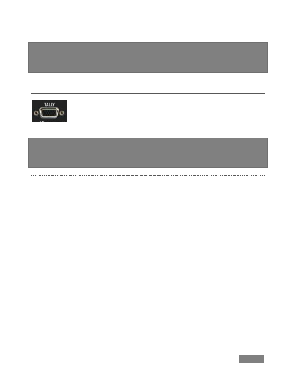
3.9.1 CONNECTION DETAILS
Here is a pin-out listing for TriCaster’s HD15 Tally connector:
Pin1 – LED1
Pin2 – LED2
Pin3 – LED3
Pin4 – LED4
Pin5 – LED5
(8-input only)
Pin6 – LED
(8-input only)
Pin7 – LED7
(8-input only)
Pin8 – LED8
(8-input only)
Pin9 – GND
Pin10 – GND
Pin11 – GPI1
Pin12 – GPI2
Pin13 – NC
Pin14 – 3.3V
(20 Ohms current limit)
Pin15 – NC
E
NGINEERING
N
OTES
Pins 1-(4 or 8) are ‘hot’ when the LED should be illuminated.
Each LED pin 1 (4 or 8) has a 200 ohm current limiting resistor inside TriCaster.
With no load (open circuit) the LED pins can reach 5V. With a typical LED load,
they can be expected to reach about 3V.
FIGURE 18