Alarm detection, Alarm codes, causes, and possible solutions – Yaskawa CIMR-LU Drives User Manual
Page 134
5 Troubleshooting
134
YASKAWA ELECTRIC TOEP C710616 38F YASKAWA AC Drive L1000A Quick Start Guide
◆ Alarm Detection
■
Alarm Codes, Causes, and Possible Solutions
Alarms are drive protection functions that do not necessarily cause the drive to stop. Once the cause of an alarm is
removed, the drive will return to the same status as before the alarm occurred.
When an alarm has been triggered, the ALM light on the digital operator display blinks and the alarm code display
flashes. If a multi-function output is set for an alarm (H2-
= 10), that output terminal will be triggered for certain
alarms.
Note: If a multi-function output is set to close when an alarm occurs (H2-
= 10), it will also close when maintenance periods are
reached, triggering alarms LT-1 through LT-4 (triggered only if H2-
= 2F).
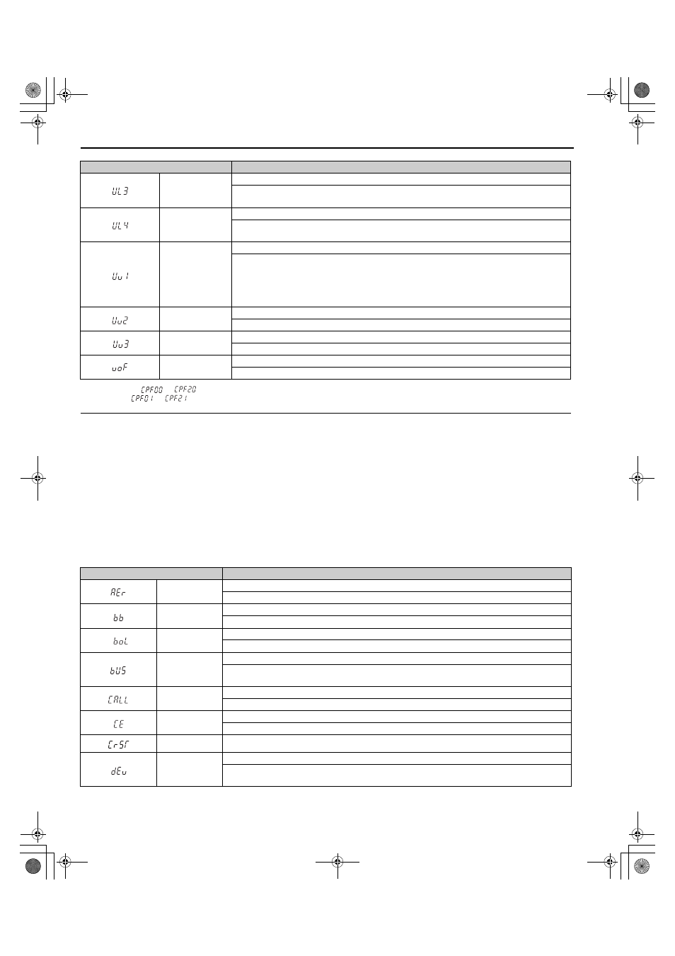
Table 36 Alarm Codes, Causes, and Possible Solutions
UL3
Undertorque Detection 1
The current has fallen below the minimum value set for torque detection (L6-02) for longer than the
allowable time (L6-03).
UL4
Undertorque Detection 2
The current has fallen below the minimum value set for torque detection (L6-05) for longer than the
allowable time (L6-06).
Uv1
DC Bus Undervoltage
One of the following conditions occurred while the drive was running:
• Voltage in the DC bus fell below the undervoltage detection level (L2-05)
• For 200 V class: approximately 190 V
• For 400 V class: approximately 380 V (350 V when E1-01 is less than 400)
• For 600 V class: approximately 500 V
Uv2
Control Power Supply Voltage Fault
Voltage is too low for the control drive input power.
Uv3
Soft-Charge Bypass Circuit Fault
The soft-charge bypass circuit failed.
voF
Output Voltage Detection Error
Problem detected with the voltage on the output side of the drive.
<1> Displayed as
or
when occurring at drive power up. When one of the faults occurs after successfully starting the drive, the display
will show
or
.
Digital Operator Display
Minor Fault Name
AEr
Communication Option Node ID Setting Error (CANopen)
Option card node address is outside the acceptable setting range.
bb
Baseblock
Drive output interrupted as indicated by an external baseblock signal.
boL
Braking Transistor Overload
The braking transistor in the drive has been overloaded.
bUS
Option Communication Error
• After initial communication was established, the connection was lost.
• Assign a Up/Down command or speed reference to the option card.
CALL
Serial Communication Stand By
Communication has not yet been established.
CE
MEMOBUS/Modbus Communication Error
Control data was not received correctly for two seconds.
CrST
Cannot Reset
dEv
Speed Deviation (when using a PG option card)
The deviation between the speed reference and speed feedback is greater than the setting in F1-10 for
longer than the time in F1-11.
Digital Operator Display
Fault Name
TOEP_C710616_38F_5_0.book 134 ページ 2013年12月4日 水曜日 午前9時56分