For details on, Table 18, Wiring the control circuit terminal – Yaskawa CIMR-LU Drives User Manual
Page 50: Yea_common
3 Electrical Installation
50
YASKAWA ELECTRIC TOEP C710616 38F YASKAWA AC Drive L1000A Quick Start Guide
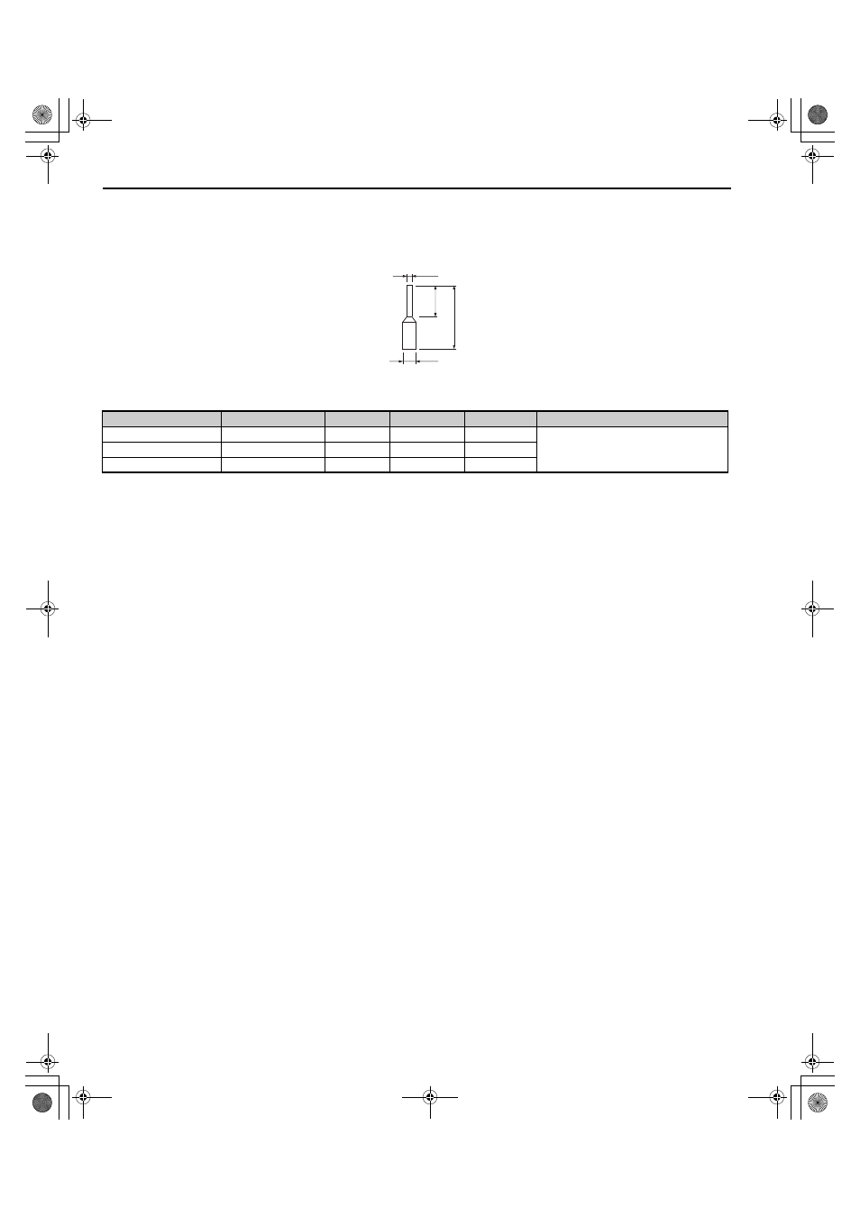
Ferrule-Type Wire Terminals
Yaskawa recommends using CRIMPFOX 6, a crimping tool manufactured by PHOENIX CONTACT, to prepare wire
ends with insulated sleeves before connecting to the drive. Refer to
for dimensions.
Figure 27
Figure 27 Ferrule Dimensions
Table 18 Ferrule Terminal Types and Sizes
■
Wiring the Control Circuit Terminal
This section describes the proper procedures and preparations for wiring the control terminals.
WARNING! Sudden Movement Hazard. Operating a drive with untested emergency circuits could result in death or serious injury.
Verify all drive fast stop circuit wiring and any additional emergency circuits before operating the drive.
WARNING! Fire hazard. Tighten all terminal screws to the specified tightening torque. Loose electrical connections could result in
death or serious injury by fire due to overheating of electrical connections.
WARNING! Electrical Shock Hazard. Do not remove covers or touch the circuit boards while the power is on. Failure to comply could
result in death or serious injury.
WARNING! Electrical Shock Hazard. Before servicing, disconnect all power to the equipment and lock out the power source. Failure to
comply may result in injury from electrical shock. Wait at least five minutes after all indicators are OFF and measure the DC bus voltage
level and main circuit terminals to confirm the circuit is safe before wiring.
WARNING! Sudden Movement and Hazard. Install additional emergency circuits separately from the drive fast stop circuits. Failure to
comply may result in personal injury.
NOTICE: Equipment Hazard. Do not connect control circuit ground terminals to the drive enclosure. Improper drive grounding can
cause control circuit malfunction.
NOTICE: Equipment Hazard. Insulate shields with heat shrink tubing or tape to prevent contact with other signal lines and equipment.
Improper wiring practices could result in drive or equipment malfunction due to short circuit.
NOTICE: Equipment Hazard. Use twisted-pair or shielded twisted-pair cables for control circuits. Improper wiring practices could result
in drive or equipment malfunction or nuisance trips.
NOTICE: Connect the shield of shielded cable to the appropriate ground terminal. Improper equipment grounding could result in drive
or equipment malfunction or nuisance trips.
NOTICE: Separate wiring for output terminals MA, MB, MC, M1 and M2 from wiring to other control circuit lines. Improper wiring
practices could result in drive or equipment malfunction or nuisance trips.
NOTICE: Separate control circuit wiring from main circuit wiring (terminals R/L1, S/L2, T/L3, B1, B2, U/T1, V/T2, W/T3, -, +1, +2) and
other high-power lines. Improper wiring practices could result in drive malfunction due to electrical interference.
NOTICE: Use a class 2 power supply (UL standard) when connecting to the control terminals. Improper application of peripheral
devices could result in drive performance degradation due to improper power supply.
NOTICE: Do not exceed 50 meters (164 feet) for the control line between the drive and the operator when using an analog signal from
a remote source to supply the frequency reference. Failure to comply could result in poor system performance.
NOTICE: Do not use unshielded cable for control wiring. Failure to comply may cause electrical interference resulting in poor system
performance. Use shielded, twisted-pair wires, and ground the shield to the ground terminal of the drive.
NOTICE: Insulate shields with tape or shrink tubing to prevent contact with other signal lines and equipment. Improper wiring practices
could result in drive or equipment malfunction due to short circuit.
Size mm
2
(AWG)
Type
Lmm (in)
d1 mm (in)
d2 mm (in)
Manufacturer
0.25 (24)
AI 0.25-6YE
10.5 (0.41)
0.8 (0.03)
2 (0.08)
PHOENIX CONTACT
0.34 (22)
AI 0.34-6TQ
10.5 (0.41)
0.8 (0.03)
2 (0.08)
0.5 (20)
AI 0.5-6WH
14 (0.55)
1.1 (0.04)
2.5 (0.10)
d1
d2
6 mm
(0.24 in.)
L
YEA_common
TOEP_C710616_38F_5_0.book 50 ページ 2013年12月4日 水曜日 午前9時56分