Using the safe disable function, C standards compliance – Yaskawa CIMR-LU Drives User Manual
Page 237
C Standards Compliance
YASKAWA ELECTRIC TOEP C710616 38F YASKAWA AC Drive L1000A Quick Start Guide
237
St
an
dar
d
s
Co
mplia
nce
C
WARNING! All safety features (including Safe Disable) should be inspected daily and periodically. If the system is not operating
normally, there is a risk of serious personal injury.
WARNING! Only a qualified technician with a thorough understanding of the drive, the instruction manual, and safety standards should
be permitted to wire, inspect, and maintain the Safe Disable input. Failure to comply may result in serious injury or death.
NOTICE: From the moment terminal inputs H1 and H2 have opened, it takes up to 1 ms for drive output to shut off completely. The
sequence set up to trigger terminals H1 and H2 should make sure that both terminals remain open for at least 1 ms in order to properly
interrupt drive output. This may result in the Safe Disable Input not activating.
NOTICE: The Safe Disable Monitor (output terminals DM+ and DM–) should not be used for any other purpose than to monitor the
Safe Disable status or to discover a malfunction in the Safe Disable inputs. The monitor output is not considered a safe output.
NOTICE: When utilizing the Safe Disable function, use only the EMC filters recommended in
EMC Filter Installation on page 219
.
■
Using the Safe Disable Function
Note: Terminals H1, H2, DM+, and DM- on 600 V class models are designed to the functionality, but are not certified to IEC/EN
61800-5-1, ISO/EN 13849 Cat. 3, IEC/EN 61508 SIL2, Insulation coordination: class 1.
The Safe Disable inputs provide a stop function in compliance with “Safe Torque Off” as defined in the IEC/EN 61800-5-
2. Safe Disable inputs have been designed to meet the requirements of the ISO/EN 13849-1, Category 3 PLd, and IEC/EN
61508, SIL2.
A Safe Disable Status Monitor for error detection in the safety circuit is also provided.
Safe Disable Circuit
Note: Terminals H1, H2, DM+, and DM- on 600 V class models are designed to the functionality, but are not certified to IEC/EN
61800-5-1,ISO/EN 13849 Cat.3, IEC/EN 61508 SIL2, Insulation coordination: class 1.
The Safe Disable circuit consists of two independent input channels that can block the output transistors (terminals H1
and H2). The input can either use the drive internal power supply or an external power supply. Use jumper S3 on the
terminal board to select between Sink or Source mode with either internal or external power supply.
A photocoupler output is available to monitor the status of the Safe Disable terminals.
for signal specifications when using this output.
Additionally a Safe Disable monitor function can be assigned to one of the digital outputs (H2-
= 58).
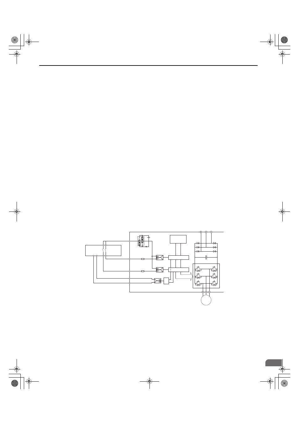
Figure 102
Figure 111 Safe Disable Function Wiring Example (Source Mode)
Safety
Outputs
Power Module P
N
M
Gate Block 2
Gate Block 1
Control
Circuit
Main Power
H1
H2
HC
Drive
Jumper S3
Setting:
SOURCE
>=1
DM+
DM-
Feedback
Safety Relay or PLC
with safety functionality
24 Vdc
TOEP_C710616_38F_5_0.book 237 ページ 2013年12月4日 水曜日 午前9時56分