U6: control monitors – Yaskawa CIMR-LU Drives User Manual
Page 213
B Parameter Table
YASKAWA ELECTRIC TOEP C710616 38F YASKAWA AC Drive L1000A Quick Start Guide
213
Par
ame
te
r Ta
ble
B
■
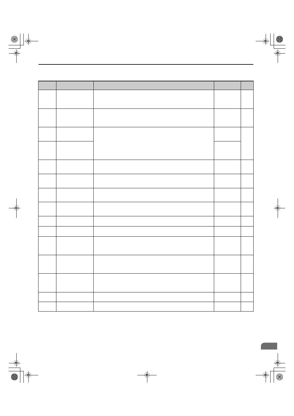
U6: Control Monitors
No.
Name
Description
Analog Output
Level
Unit
U6-01
<9> Values shown here are for 200 V class drives. Double the value when using a 400 V class drive. Multiply value by 2.875 for 600 V class drives.
Motor Secondary
Current (Iq)
Displays the value of the motor secondary current (Iq). Motor rated secondary
current is 100%.
10 V: Motor
secondary rated
current
(-10 to +10 V)
0.1%
U6-02
Motor Excitation
Current (Id)
Displays the value calculated for the motor excitation current (Id). Motor rated
secondary current is 100%.
10 V: Motor
secondary rated
current
(-10 to +10 V)
0.1%
U6-03
Speed Control Loop
Input
Displays the input and output values of the speed control loop.
10 V:
Max frequency
(-10 to +10 V)
0.01%
U6-04
Speed Control Loop
Output
10 V: Motor
secondary rated
current
(-10 to +10 V)
U6-05
Output Voltage
Reference (Vq)
Output voltage reference (Vq) for the q-axis.
10 V:
200 Vrms
(-10 to +10 V)
0.1 Vac
U6-06
Output Voltage
Reference (Vd)
Output voltage reference (Vd) for the d-axis.
10 V:
200 Vrms
(-10 to +10 V)
0.1 Vac
U6-07
q-Axis Current
Controller Output
Displays the output value for current control relative to motor secondary current
(q-axis).
10 V:
200 Vrms
(-10 to +10 V)
0.1%
U6-08
d-Axis Current
Controller Output
Displays the output value for current control relative to motor secondary current
(d-axis).
10 V:
200 Vrms
(-10 to +10 V)
0.1%
U6-13
Flux Position Detection
(sensor)
Monitors the value of the flux position detection (sensor).
10 V: 180 deg
-10 V: -180 deg
0.1 deg
U6-18
Speed Detection PG1
Counter
Monitors the number of pulses for speed detection (PG1).
10 V: 65536
1 pulse
U6-22
Position Lock
Deviation Counter
Displays how far the rotor has moved from its last position in PG pulses
(multiplied by 4).
10 V: No. of
pulses per
revolution
(-10 to +10 V)
1 pulse
U6-25
Feedback Control
Output
Output monitor for the speed control loop.
10 V: Motor
secondary rated
current
(-10 to +10 V)
0.01%
U6-26
Inertia Compensation
Output
Output monitor for Inertia Compensation.
10 V: Motor
secondary rated
current
(-10 to +10 V)
0.01%
U6-56
Speed Feedback
Compensation Output
Displays observed speed when n5-07=1 or 2.
10 V: Max
output frequency
0.01%
U6-80
to U6-99
Option Monitor 1 to 20 Monitors reserved to display data from option cards.
No signal output
available
–
TOEP_C710616_38F_5_0.book 213 ページ 2013年12月4日 水曜日 午前9時56分