S4: rescue operation – Yaskawa CIMR-LU Drives User Manual
Page 201
B Parameter Table
YASKAWA ELECTRIC TOEP C710616 38F YASKAWA AC Drive L1000A Quick Start Guide
201
Par
ame
te
r Ta
ble
B
■
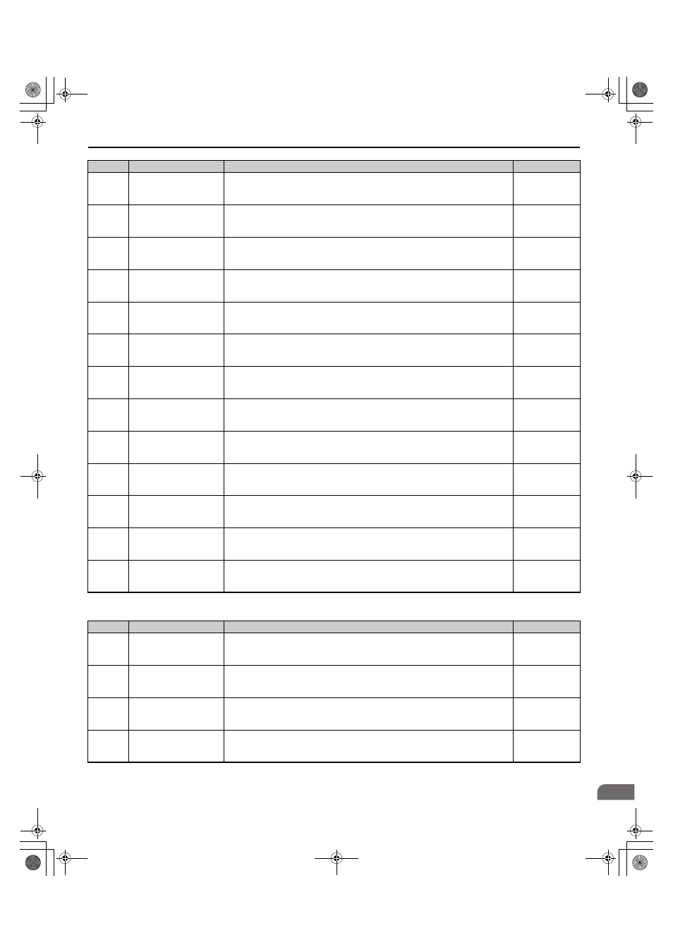
S4: Rescue Operation
S3-25
DC Injection Gain in
Regenerative Operation
Sets the gain level applied to the DC injection current at stop (S1-03) for when the
load is 100% regenerative. The current applied during DC Injection at stop is
determined as S1-03
× S3-25.
Default: 100%
Min: 0%
Max: 400%
S3-26
DC Injection Gain in
Motoring Operation
Sets the gain level applied to the DC injection current at stop (S1-03) for when the
load is 100% motoring. The current applied during DC Injection at stop is determined
as S1-03
× S3-26.
Default: 20%
Min: 0%
Max: 400%
S3-27
Torque Compensation
Value with Load Condition
1
Used for starting torque compensation utilizing a load cell signal. Sets the torque
compensation value for load condition 1.
Default: –50%
Min: –100%
Max: 100%
S3-28
Torque Compensation
Value with Load Condition
2
Used for starting torque compensation utilizing a load cell signal. Sets the torque
compensation value for load condition 2.
Default: 50%
Min: –100%
Max: 100%
S3-29
Analog Input from Load
Cell with Load Condition 1
Used for starting torque compensation utilizing a load cell signal. Sets the analog
signal level from the load cell for load condition 1.
Default: 0.0%
Min: –100%
Max: 100%
S3-30
Analog Input from Load
Cell with Load Condition 2
Used for starting torque compensation utilizing a load cell signal. Sets the analog
signal level from the load cell for load condition 2.
Default: 100.0%
Min: –100.0%
Max: 100%
S3-34
Anti-Rollback Torque Bias
1
Sets the Anti-Rollback Bias applied at small position deviations during Position Lock
at start.
Default: 0.0%
Min: 0.0%
Max: 100.0%
S3-35
Anti-Rollback Torque Bias
2
Sets the Anti-Rollback Bias applied at large position deviations during Position Lock
at start.
Default: 0.0%
Min: 0.0%
Max: 100.0%
S3-37
Position Deviation Level to
Apply ARB Torque Bias 1
Sets the position deviation level to active at Anti-Rollback Torque Bias 1 (S3-34).
Default: 0
Min: 0
Max: 32767
S3-38
Position Deviation Level to
Apply ARB Torque Bias 2
Determines the position deviation level for when the drive should switch from the
torque bias set in S3-34 to the torque bias set in S3-35.
Default: 0
Min: 0
Max: 32767
S3-39
Anti-Rollback Integral
Gain
Determines the drive’s responsiveness for Anti-Rollback during Position Lock.
Default: 0.00
Min: –30.00
Max: 30.00
S3-40
Anti-Rollback Movement
Detection
Sets the amount of pulses for movement detection during Anti-Rollback.
Default: 1 pulse
Min: 0 pulse
Max: 100 pulses
S3-41
Position Lock Gain at Start
2 Reduction
Sets a reduction factor for the Position Lock Gain at Start 2 (Anti-Rollback Gain) set
in parameter S3-02.
Default: 0.50
Min: 0.00
Max: 1.00
No.
Name
Description
Setting
S4-01
Light Load Direction
Search Selection
0: Disabled
1: Enabled
2: Enabled for Motor 1 only
Default: 0
Min: 0
Max: 2
S4-02
Light Load Direction
Search Method
Determines how the drive detects the light load direction.
0: Output Current
1: Regenerative direction detection
Default: 1
Min: 0
Max: 1
S4-03
Light Load Direction
Search Time
Sets the time to perform Light Load Direction Search.
Default: 1.0 s
Min: 0.0 s
Max: 5.0 s
S4-04
Light Load Direction
Search Speed Reference
Sets the speed reference to use during Light Load Direction Search.
Min: 0.00%
Max: 20.00%
No.
Name
Description
Setting
TOEP_C710616_38F_5_0.book 201 ページ 2013年12月4日 水曜日 午前9時56分