Yaskawa CIMR-LU Drives User Manual
Page 235
C Standards Compliance
YASKAWA ELECTRIC TOEP C710616 38F YASKAWA AC Drive L1000A Quick Start Guide
235
St
an
dar
d
s
Co
mplia
nce
C
L1-01: Motor Overload Protection Selection
The drive has an electronic overload protection function (oL1) based on time, output current, and output speed, which
protects the motor from overheating. The electronic thermal overload function is UL-recognized, so it does not require an
external thermal relay for single motor operation.
This parameter selects the motor overload curve used according to the type of motor applied.
Table 68 Overload Protection Settings
When connecting the drive to more than one motor for simultaneous operation, disable the electronic overload protection
(L1-01 = 0) and wire each motor with its own motor thermal overload relay.
Enable the motor overload protection (L1-01 = 1 to 3, 5) when connecting the drive to a single motor, unless another
motor overload preventing device is installed. The drive electronic thermal overload function causes an oL1 fault, which
shuts off the output of the drive and prevents additional overheating of the motor. The motor temperature is continually
calculated while the drive is powered up.
L1-02: Motor Overload Protection Time
Setting Range: 0.1 to 5.0 min
Factory Default: 1.0 min
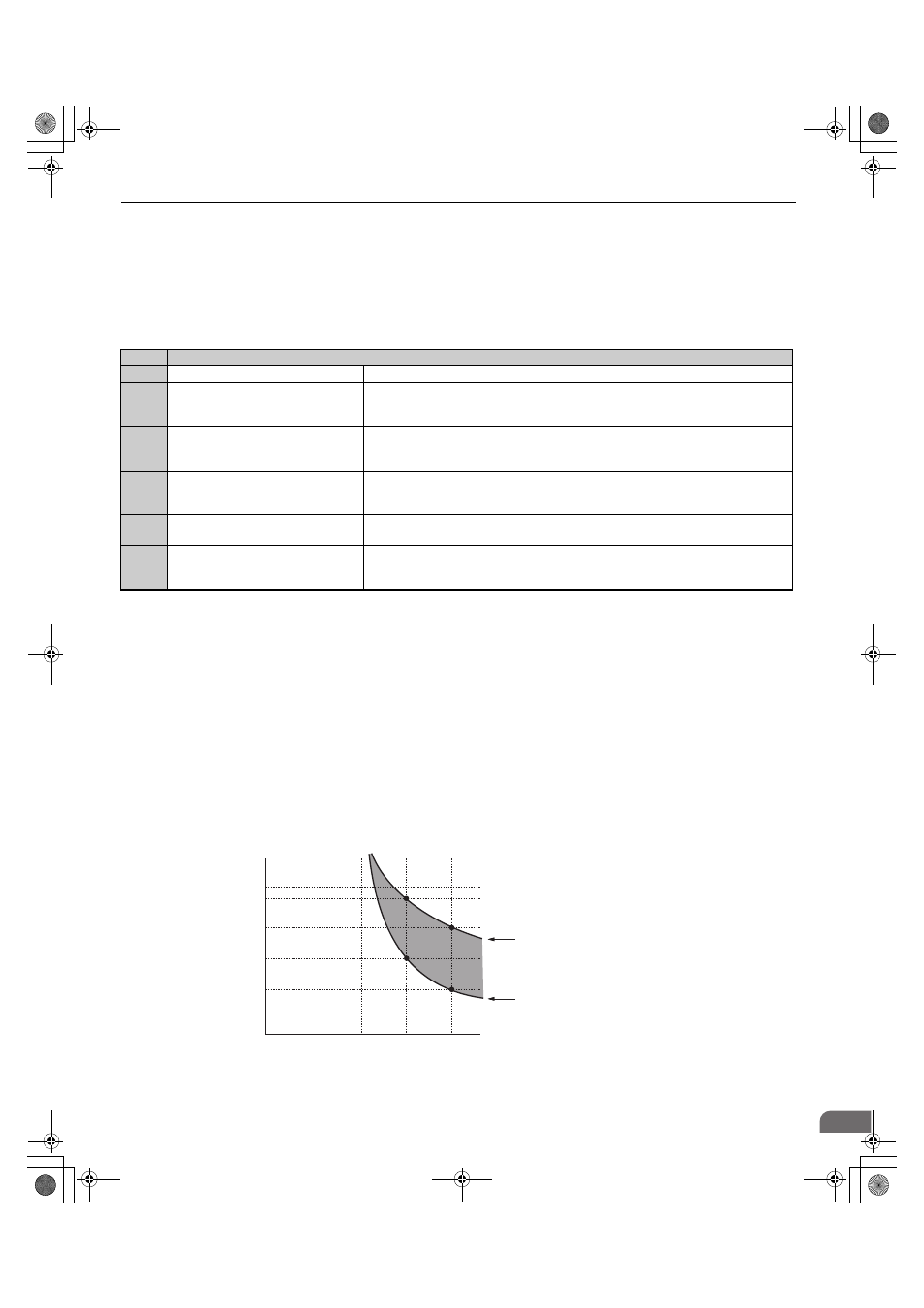
Parameter L1-02 determines how long the motor is allowed to operate before the oL1 fault occurs when the drive is
running at 60 Hz and at 150% of the full load amp rating (E2-01/E5-03) of the motor. Adjusting the value of L1-02 can
shift the set of oL1 curves up the y axis of the diagram below, but will not change the shape of the curves.
Figure 101
Figure 110 Protection Operation Time for General Purpose Motors at the Rated Output Frequency
Setting
Description
0
Disabled
Disabled the internal motor overload protection of the drive.
1
Standard fan-cooled motor (default)
Selects protection characteristics for a standard self cooled motor with limited cooling
capabilities when running below the rated speed. The motor overload detection level (oL1) is
automatically reduced when running below the motor rated speed.
2
Drive duty motor with a speed range of
1:10
Selects protection characteristics for a motor with self-cooling capability within a speed
range of 10:1. The motor overload detection level (oL1) is automatically reduced when
running below 1/10 of the motor rated speed.
3
Vector motor with a speed range of 1:100
Selects protection characteristics for a motor capable of cooling itself at any speed —
including zero speed (externally cooled motor). The motor overload detection level (oL1) is
constant over the entire speed range.
5
Permanent Magnet motor with constant
torque
Selects protection characteristics for a constant torque PM motor. The motor overload
detection level (oL1) is constant over the whole speed range.
6
Standard fan cooled motor (50 Hz)
Selects protection characteristics for a standard self cooled motor with limited cooling
capabilities when running below the rated speed. The motor overload detection level (oL1) is
automatically reduces when running below the motor rated speed.
Operation time (minutes)
Cold start
(Characteristics when an overload occurs
at a complete stop)
Hot start
(Characteristics when an overload occurs
during continuous operation at 100%)
Motor current (%)
E2-01 = 100% motor current
10
7
3
1
0.4
0.1
0
100
150
200
TOEP_C710616_38F_5_0.book 235 ページ 2013年12月4日 水曜日 午前9時56分