Yaskawa CIMR-LU Drives User Manual
Page 45
3 Electrical Installation
YASKAWA ELECTRIC TOEP C710616 38F YASKAWA AC Drive L1000A Quick Start Guide
45
El
ec
tr
ical
I
n
st
al
lat
io
n
3
Cable Length Between Drive and Motor
Voltage drop along the motor cable may cause reduced motor torque when the wiring between the drive and the motor is
too long, especially at low frequency output. This can also be a problem when motors are connected in parallel with a
fairly long motor cable. Drive output current will increase as the leakage current from the cable increases. An increase in
leakage current may trigger an overcurrent situation and weaken the accuracy of the current detection.
Adjust the drive carrier frequency according to
. If the motor wiring distance exceeds 100 m (328 ft.) because of
the system configuration, reduce the ground currents.
Refer to C6: Carrier Frequency on page 171
.
NOTICE: Equipment Hazard. Separate motor and/or braking circuit wiring (terminals, U/T1, V/T2, W/T3, +3, +2, +1,(-), B1, B2, from all
other wiring. Place motor wiring within its own conduit or cable tray with appropriate divider, and use shielded motor cable where
appropriate. Improper wiring practices could result in malfunction of drive due to electrical interference.
Table 13 Cable Length Between Drive and Motor
Note: When setting carrier frequency for drives running multiple motors, calculate cable length as the total wiring distance to all
connected motors.
Ground Wiring
Follow the precautions to wire the ground for one drive or a series of drives.
WARNING! When using an EMC filter, the leakage current exceeds 3.5 mA. Therefore, according to IEC/EN 61800-5-1, at least one of
the conditions below must be satisfied:
a) The cross-section of the protective earthing conductor must be at least 10 mm
2
(Cu) or 16 mm
2
(Al).
b) The power supply must be disconnected automatically in case of discontinuity of the protective earthing conductor.
WARNING! Electrical Shock Hazard. Always use a ground wire that complies with technical standards on electrical equipment and
local installation regulations. Minimize the length of the ground wire. Improper equipment grounding may cause dangerous electrical
potentials on equipment chassis, which could result in death or serious injury.
WARNING! Electrical Shock Hazard. Be sure to ground the drive ground terminal (200 V class: Ground to 100
Ω
or less, 400 V class:
Ground to 10
Ω
or less, and 600 V class: ground to 10
Ω
or less). Improper equipment grounding may cause dangerous electrical
potentials on equipment chassis, which could result in death or serious injury.
NOTICE: Do not share the ground wire with other devices such as welding machines or large-current electrical equipment. Improper
equipment grounding could result in drive or equipment malfunction due to electrical interference.
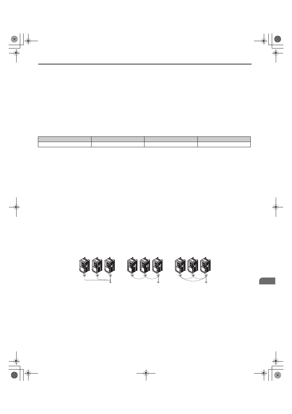
NOTICE: When using more than one drive, ground multiple drives according to instructions. Improper equipment grounding could
result in abnormal operation of drive or equipment.
Refer to
when using multiple drives. Do not loop the ground wire.
Figure 23
Figure 23 Multiple Drive Wiring
Cable Length
50 m (164 ft.) or less
100 m (328 ft.) or less
Greater than 100 m (328 ft.)
Carrier Frequency
15 kHz or less
5 kHz or less
2 kHz or less
OK
OK
Not OK
TOEP_C710616_38F_5_0.book 45 ページ 2013年12月4日 水曜日 午前9時56分