Yaskawa CIMR-LU Drives User Manual
Page 88
4 Start-Up Programming & Operation
88
YASKAWA ELECTRIC TOEP C710616 38F YASKAWA AC Drive L1000A Quick Start Guide
is divided into time zones.
explains the sequence in each time zone.
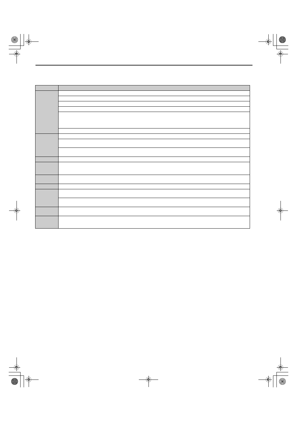
Table 29 Time Zones for Brake Sequence Using Torque Compensation at Start
Adjusting the Torque Compensation at Start
CAUTION! Set all motor-related parameters (the E -
parameters) and perform a test run before fine-tuning the torque
compensation at start. Adjusting the torque compensation prematurely may result in faulty performance.
To use torque compensation at start, apply at least 50% of the maximum weight to the elevator car and set the drive
according to the Load Condition 2 procedure below. If using a voltage signal to the analog input terminals as a load
sensor, then that input signal will determine the rate of torque compensation applied according to S3-27 and S3-28.
Before the torque compensation function can be used, the analog input scaling must be adjusted to the load sensor output.
This can be done by bringing the elevator into two different load conditions and teaching the corresponding analog input
value and torque reference value to the drive.
Note: 1. This torque compensation requires a closed loop control mode (CLV, CLV/PM).
2. The torque compensation value is limited to 120%.
Time Zone
Description
t1
Up or Down command is issued.
Safe Disable terminals H1-HC and H2-HC must be set and Baseblock must be disabled (digital inputs set to H1-
= 8/9).
Speed reference must be selected by multi-function input terminals.
Output contactor control signal is set (H2-
= 51) by the drive.
Drive waits for the “Motor Contactor Feedback” signal (H1-
= 56) to be issued. If the motor contactor feedback is not
received within t1, or if the feedback signal is on before the contactor control command has been issued, an SE1 fault is triggered.
If the motor contactor feedback signal is not used, then the drive waits for the operation start delay time set in S1-10 to pass, then
proceeds to the next step.
The drive reads the torque value from the analog input (load cell).
t2
After the delay time set in S1-10 has passed, the drive outputs current to the motor. Position Lock begins.
The torque value from the analog input is latched and internal torque compensation value is increased from zero to the latched
value using the time constant set in S3-10.
After the internal torque compensation level reaches the latched value, the drive sets the “Brake Control” output (H2-
= 50) in
order to release the brake.
t3
The brake is released and the drive executes Position Lock until the time set in S1-04 has passed.
t4
The drive accelerates up to the selected speed.
After the torque compensation diminish speed level (S3-14) is reached during acceleration, the internal torque compensation
value is reduced in accordance with the time constant set in S3-10.
t5
Leveling speed is selected. The drive decelerates to the leveling speed and maintains that speed until the Up or Down command is
removed.
t6
The Up or Down signal is cleared. The drive decelerates to zero speed.
t7
The motor speed reaches the zero speed level (S1-01).
DC Injection Braking or Position Lock is then executed for the time set in S1-05.
After the delay time to close the brake set in S1-07 has passed, the drive clears the “Brake Control” output (H2-
= 50). The
brake applies.
t8
The drive continues DC Injection or Position Lock until the time S1-05 has passed. When S1-05 has passed the drive output is
shut off.
t9
After the delay for the magnetic contactor set in S1-11 has passed, the drive resets the output terminal set for “Output Contactor
Control” (H2-
= 51).
The Safe Disable Inputs can be cleared and Baseblock can be enabled.
TOEP_C710616_38F_5_0.book 88 ページ 2013年12月4日 水曜日 午前9時56分