Yea_common – Yaskawa CIMR-LU Drives User Manual
Page 48
3 Electrical Installation
48
YASKAWA ELECTRIC TOEP C710616 38F YASKAWA AC Drive L1000A Quick Start Guide
Output Terminals
lists the output terminals on the drive. Text in parenthesis indicates the default setting for each multi-function
output.
Note: Multi-function relay output terminals are rated at a minimum of 10 mA. If less than 10 mA is required, use the photocoupler
outputs (P1-C1, P2-C2). Using the wrong current output level may cause the output to malfunction when the terminal is activated.
Table 15 Control Circuit Output Terminals
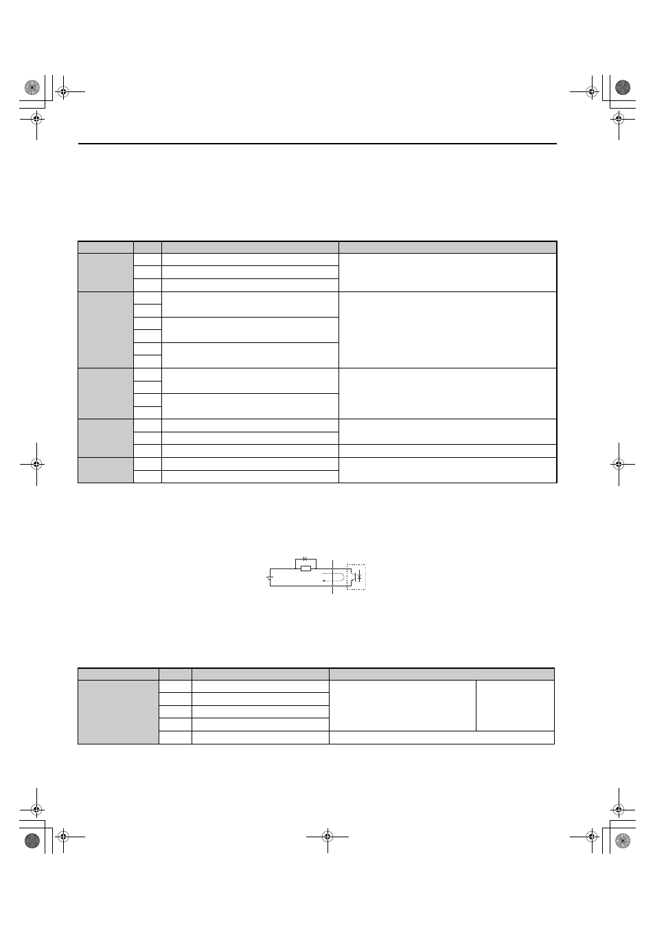
Figure 25
Figure 25 Connecting a Suppression Diode
Serial Communication Terminals
Table 16 Control Circuit Terminals: Serial Communications
Type
<1> Refrain from assigning functions to terminals M1 thru M6 that involve frequent switching, as doing so may shorten relay performance life.
Switching life is estimated at 200,000 times (assumes 1 A, resistive load).
<2> Connect a suppression diode as shown in
when driving a reactive load such as a relay coil. Make sure the diode rating is greater than
the circuit voltage.
<3> Terminals H1, H2, DM+, and DM- on 600 V class models are designed to the functionality, but are not certified to IEC/EN 61800-5-1,ISO/EN
13849 Cat.3, IEC/EN 61508 SIL2, Insulation coordination: class 1.
No.
Terminal Name (Function)
Function (Signal Level) Default Setting
Fault Relay
MA
N.O.
30 Vdc, 10 mA to 1 A; 250 Vac, 10 mA to 1 A
Minimum load: 5 Vdc, 10 mA
MB
N.C. output
MC
Fault output common
Multi-Function
Relay Output
M1
Multi-function relay output 1 (Brake release
command)
Contact relay output
30 Vdc, 10 mA to 1 A
250 Vac, 10 mA to 1 A
Minimum load: 5 Vdc, 10 mA
M2
M3
Multi-function relay output 2 (Output contactor close
command)
M4
M5
Multi-function relay output 3 (Drive ready)
M6
Multi-Function
Photocoupler
Output
P1
Photocoupler output 1 (During Frequency output)
48 Vdc, 2 to 50 mA
C1
P2
Photocoupler output 2 (Not Used/Through Mode)
C2
Monitor Output
FM
Analog monitor output 1 (Output speed)
-10 to +10 Vdc or 0 to +10 Vdc
AM
Analog monitor output 2 (Output current)
AC
Monitor common
0 V
Safety Monitor
Output
DM+ Safety monitor output
Outputs status of Safe Disable function. Closed when both Safe
Disable channels are closed. Up to +48 Vdc 50 mA
DM-
Safety monitor output common
A – External power, 48 V max.
C – Coil
B – Suppression diode
D – 50 mA or less
Type
<1> Enable the termination resistor in the last drive in a MEMOBUS network by setting DIP switch S2 to the ON position.
No.
Signal Name
Function (Signal Level)
MEMOBUS/Modbus
Communication
R+
Communications input (+)
MEMOBUS/Modbus communication: Use
an RS-485 or RS-422 cable to connect the
drive.
RS-485/422
MEMOBUS/Modbus
communication
protocol
115.2 kbps (max.)
R-
Communications input (-)
S+
Communications output (+)
S-
Communications output (-)
IG
Shield ground
0 V
A
B
C
D
YEA_common
TOEP_C710616_38F_5_0.book 48 ページ 2013年12月4日 水曜日 午前9時56分