Yaskawa CIMR-LU Drives User Manual
Page 47
3 Electrical Installation
YASKAWA ELECTRIC TOEP C710616 38F YASKAWA AC Drive L1000A Quick Start Guide
47
El
ec
tr
ical
I
n
st
al
lat
io
n
3
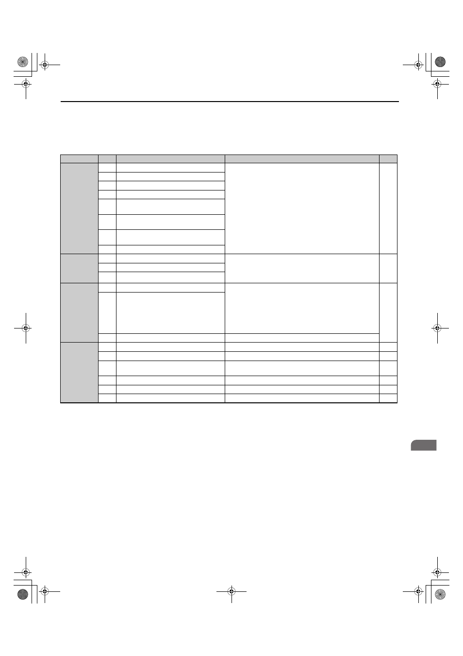
Input Terminals
lists the input terminals on the drive. Text in parenthesis indicates the default setting for each multi-function
input.
Table 14 Control Circuit Input Terminals
Type
<1> Setting jumper S3 for an external power supply makes the wire jumper between terminals H1, H2, and HC ineffective. Remove the wire jumper
and connect an external power supply that can supply terminals H1, H2, and HC continuously.
<2> Terminals H1, H2, DM+, and DM- on 600 V class models are designed to the functionality, but are not certified to IEC/EN 61800-5-1,ISO/EN
13849 Cat.3, IEC/EN 61508 SIL2, Insulation coordination: class 1.
No.
Terminal Name (Function)
Function (Signal Level) Default Setting
Page
Digital Inputs
S1
Up Command (Closed: Up, Open: Stop)
Photocoupler
24 Vdc, 8 mA
Use the wire link between terminals SC and SN or between SC
and SP to select sinking or sourcing, and to select the power
supply.
S2
Down Command (Closed: Down, Open: Stop)
S3
Multi-function input 1 (External Fault)
S4
Multi-function input 2 (Fault Reset)
S5
Multi-function input 3 (Multi-Step Speed
Reference 1)
S6
Multi-function input 4 (Multi-Step Speed
Reference 2)
S7
Multi-function input 5 (Multi-Step Speed
Reference 3)
S8
Multi-function input 6 (Not used)
Digital Input
Power Supply
SC
Multi-function input common
24 Vdc, 150 mA (only when DI-A3 is not used)
Use the wire jumper between terminals SC and SN or between SC
and SP to select sinking or sourcing, and to select the power
supply.
SN
0 V
SP
+24 Vdc
Safe Disable
Inputs
H1
Safe Disable input 1
24 Vdc, 8 mA
One or both open: Drive output disabled
Both closed: Normal operation
Internal impedance: 3.3 k
Ω
Off time of at least 1 ms
Set the S3 jumper to select sinking or sourcing, and to select the
power supply.
H2
Safe Disable input 2
HC
Safe Disable function common
Common for the Safe Disable function
Analog Inputs
+V
Power supply for analog inputs
10.5 Vdc (max allowable current 20 mA)
-V
Power supply for analog inputs
-10.5 Vdc (max allowable current 20 mA)
–
A1
Multi-function analog input 1 (Speed
reference bias)
-10 to 10 Vdc, 0 to 10 Vdc (input impedance: 20 k
Ω)
–
A2
Multi-function analog input 2 (Not used)
-10 to 10 Vdc, 0 to 10 Vdc (input impedance: 20 k
Ω)
–
AC
Analog input common
0 V
–
E (G) Ground for shielded lines and option cards
–
–
TOEP_C710616_38F_5_0.book 47 ページ 2013年12月4日 水曜日 午前9時56分