Wiring checklist – Yaskawa CIMR-LU Drives User Manual
Page 55
3 Electrical Installation
YASKAWA ELECTRIC TOEP C710616 38F YASKAWA AC Drive L1000A Quick Start Guide
55
El
ec
tr
ical
I
n
st
al
lat
io
n
3
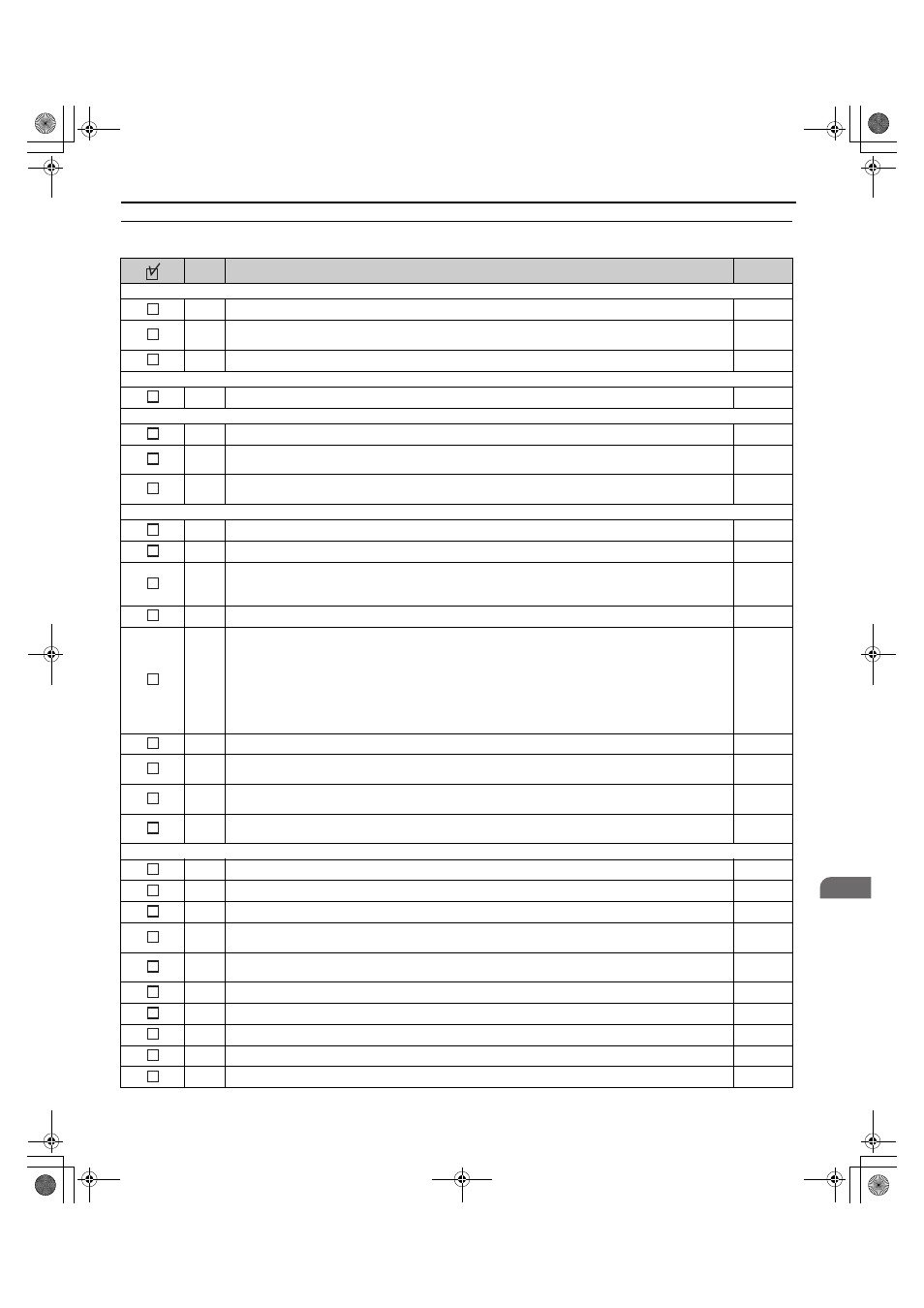
◆ Wiring Checklist
No.
Item
Page
Drive, peripherals, option cards
1
Check drive model number to ensure receipt of correct model.
–
2
Make sure you have the correct braking resistors, DC link choke, noise filters, and other peripheral devices
installed.
–
3
Check the option card model number.
–
Installation area and physical setup
4
Ensure that the area surrounding the drive complies with specifications.
Power supply voltage, output voltage
5
The voltage from the power supply should be within the input voltage specification range of the drive.
–
6
The voltage rating for the motor should match the drive output specifications.
7
Verify that the drive is properly sized to run the motor.
Main circuit wiring
8
Confirm proper branch circuit protection as specified by national and local codes.
9
Properly wire the power supply to drive terminals R/L1, S/L2, and T/L3.
10
Properly wire the drive and motor together.
The motor lines and drive output terminals R/T1, V/T2, and W/T3 should match in order to produce the
desired phase order. If the phase order is incorrect, the drive will rotate in the opposite direction.
11
Use 600 Vac vinyl-sheathed wire for the power supply and motor lines.
12
Use the correct wire gauges for the main circuit.
Refer to Wire Gauges and Tightening Torque on page 36
• Consider the amount of voltage drop when selecting wire gauges. Increase the wire gauge when the voltage
drop is greater than 2% of motor rated voltage. Ensure the wire gauge is suitable for the terminal block. Use
the following formula to calculate the amount of voltage drop:
Line drop voltage (V) = 3
× wire resistance (Ω/km) × wire length (m) × current (A) × 10
-3
• If the cable between the drive and motor exceeds 50 m (164 feet), adjust the carrier frequency set to C6-02
accordingly.
13
Properly ground the drive. Review page
14
Tightly fasten all terminal screws (control circuit terminals, grounding terminals).
Refer to Wire Gauges and Tightening Torque on page 36
15
Install a magnetic contactor when using a dynamic braking option. Properly install the resistor and ensure that
overload protection shuts off the power supply using the magnetic contactor.
–
16
Verify phase advancing capacitors, input noise filters, or ground fault circuit interrupters are NOT installed on
the output side of the drive.
–
Control circuit wiring
17
Use twisted-pair line for all drive control circuit wiring.
18
Connect the shields of shielded wiring to the ground terminal (E [G] ).
19
Properly wire any option cards.
20
Check for any other wiring mistakes.
Only use a multimeter to check wiring.
–
21
Properly fasten the control circuit terminal screws in the drive.
Refer to Wire Gauges and Tightening Torque on page 36
22
Pick up all wire clippings.
–
23
Ensure that no frayed wires on the terminal block are touching other terminals or connections.
–
24
Properly separate control circuit wiring and main circuit wiring.
–
25
Analog signal line wiring should not exceed 50 m (164 ft.).
–
26
Safe Disable input wiring should not exceed 30 m (98 ft.).
–
TOEP_C710616_38F_5_0.book 55 ページ 2013年12月4日 水曜日 午前9時56分