Maintenance – Yaskawa CIMR-LU Drives User Manual
Page 144
6 Periodic Inspection & Maintenance
144
YASKAWA ELECTRIC TOEP C710616 38F YASKAWA AC Drive L1000A Quick Start Guide
Performance Life Monitors Maintenance Monitors
The drive calculates the maintenance period for components that may require replacement during the life of the drive. A
percentage of the maintenance period is displayed on the digital operator by viewing the appropriate monitor parameter.
When the maintenance period reaches 100%, there is increased risk that the drive may malfunction. Yaskawa
recommends checking the maintenance period regularly to ensure maximum performance life.
Refer to Recommended Periodic Inspection on page 142
for more details.
Table 43 Performance Life Monitors Used for Component Replacement
Alarm Outputs for Maintenance Monitors
An output can be set up to inform the user when a specific components has neared its expected performance life.
When one of multi-function digital output terminals has been assigned the maintenance monitor function (H2-
= 2F),
the terminal will close when the cooling fan, DC bus capacitors, or DC bus pre-charge relay reach 90% of the expected
performance life, or when the IGBTs have reached 50% of their expected performance life. Additionally the digital
operator will display an alarm like shown in
to indicate the specific components that may need maintenance.
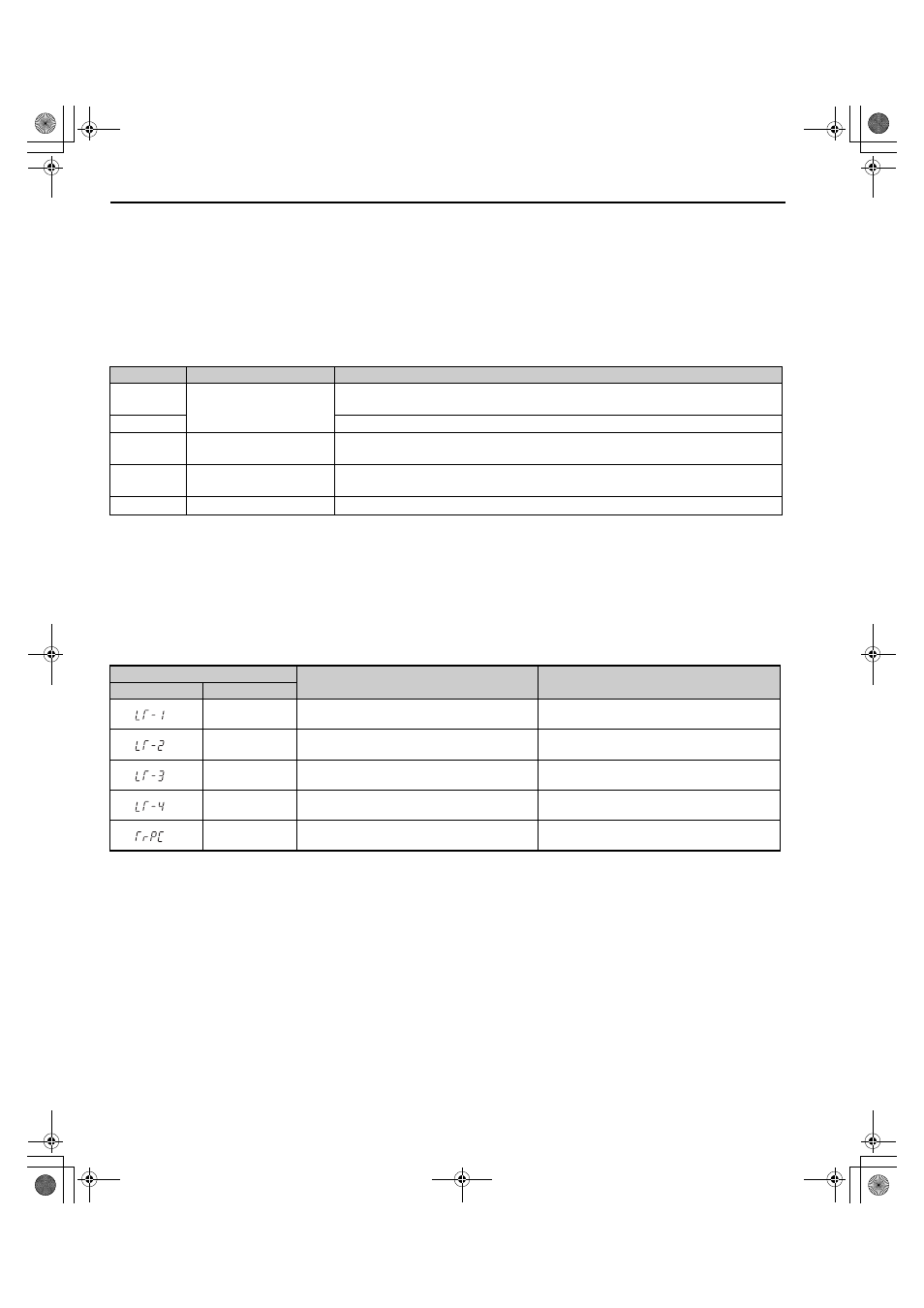
Table 44 Maintenance Alarms
Related Drive Parameters
Use parameters o4-03, o4-05, o4-07, and o4-09 to reset a Maintenance Monitor to zero after replacing a specific
component.
Refer to Parameter Table on page 165
for details on parameter settings.
NOTICE: If these parameters are not reset after the corresponding parts have been replaced, the Maintenance Monitor function will
continue to count down the performance life from the value that was reached with the old part. If the Maintenance Monitor is not reset,
the drive will not have the correct value of the performance life for the new component.
Parameter
Component
Contents
U4-03
Cooling Fan, Circulation Fan,
Control Board Cooling Fan
Displays the accumulated operation time of the fan, from 0 to 99999 hours. This value is
automatically reset to 0 once it reaches 99999.
U4-04
Displays the accumulated fan operation time as a percentage of the specified maintenance period.
U4-05
DC Bus Capacitors
Displays the accumulated time the capacitors are used as a percentage of the specified
maintenance period.
U4-06
Inrush (pre-charge) Relay
Displays the number of times the drive is powered up as a percentage of the performance life of
the inrush circuit.
U4-07
IGBT
Displays the percentage of the maintenance period reached by the IGBTs.
Alarm Display
Function
Corrective Action
LED Operator
LCD Operator
<1> This alarm message will be output only if the Maintenance Monitor function is assigned to one of the digital outputs (H2-
= 2F). The alarm
will also trigger a digital output that is programmed for alarm indication (H2-
= 10).
<2> This alarm message will always be output, even if the Maintenance Monitor function is not assigned to any of the digital outputs (H2-
=
2F). The alarm will also trigger a digital output that is programmed for alarm indication (H2-
= 10).
LT-1
The cooling fans have reached 90% of their
designated lifetime.
Replace the cooling fan.
LT-2
The DC bus capacitors have reached 90% of their
designated lifetime.
Replace the drive.
LT-3
The DC bus charge circuit has reached 90% of its
designated lifetime.
Replace the drive.
LT-4
The IGBTs have reached 50% of their designated
lifetime.
Check the load, carrier frequency, and output
frequency.
TrPC
The IGBTs have reached 90% of their designated
lifetime.
Replace the drive.
TOEP_C710616_38F_5_0.book 144 ページ 2013年12月4日 水曜日 午前9時56分