Drive replacement, Serviceable parts, Terminal board – Yaskawa CIMR-LU Drives User Manual
Page 145: Yea_comm on
6 Periodic Inspection & Maintenance
YASKAWA ELECTRIC TOEP C710616 38F YASKAWA AC Drive L1000A Quick Start Guide
145
Pe
ri
odic
Inspe
c
ti
on &
Maint
ena
nc
e
6
◆ Drive Replacement
■
Serviceable Parts
The drive contains some serviceable parts. The following parts can be replaced over the life span of the drive:
• Terminal board I/O PCBs
• Cooling fan(s)
• Front cover
Replace the drive if the main power circuitry is damaged. Contact your local Yaskawa representative before replacing
parts if the drive is still under warranty. Yaskawa reserves the right to replace or repair the drive according to Yaskawa
warranty policy.
■
Terminal Board
CAUTION! Crush Hazard. Carrying the drive by the front cover may cause the main body of the drive to fall, resulting in minor or
moderate injury. Always hold the case when carrying the drive.
NOTICE: Correctly set parameter o2-04 when replacing the control terminal board. Failure to comply may result in drive damage due to
lack of protective functions and poor drive performance.
The drive has a modular I/O terminal block that facilitates quick drive replacement. The terminal board contains on-board
memory that stores all drive parameter settings and allows the parameters to be saved and transferred to the replacement
drive. To transfer the terminal board, disconnect the terminal board from the damaged drive then reconnect it to the
replacement drive. Once transferred, there is no need to manually reprogram the replacement drive.
Note: If the damaged drive and the new replacement drive are have different capacities, the data stored in the control terminal board
cannot be transferred to the new drive and an oPE01 error will appear on the display. The control terminal board can still be used,
but parameter setting from the old drive cannot be transferred. The replacement drive must be initialized and manually
programmed.
Figure 72
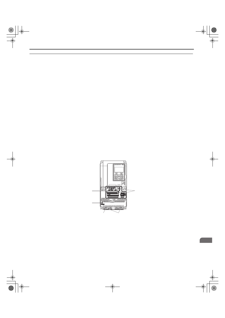
Figure 79 Terminal Board
A – Removable terminal board
D – Bottom cover screws
B – Charge LED
E – Control terminal board locking screws
C – Bottom cover
E
D
A
B
C
YEA_comm
on
TOEP_C710616_38F_5_0.book 145 ページ 2013年12月4日 水曜日 午前9時56分