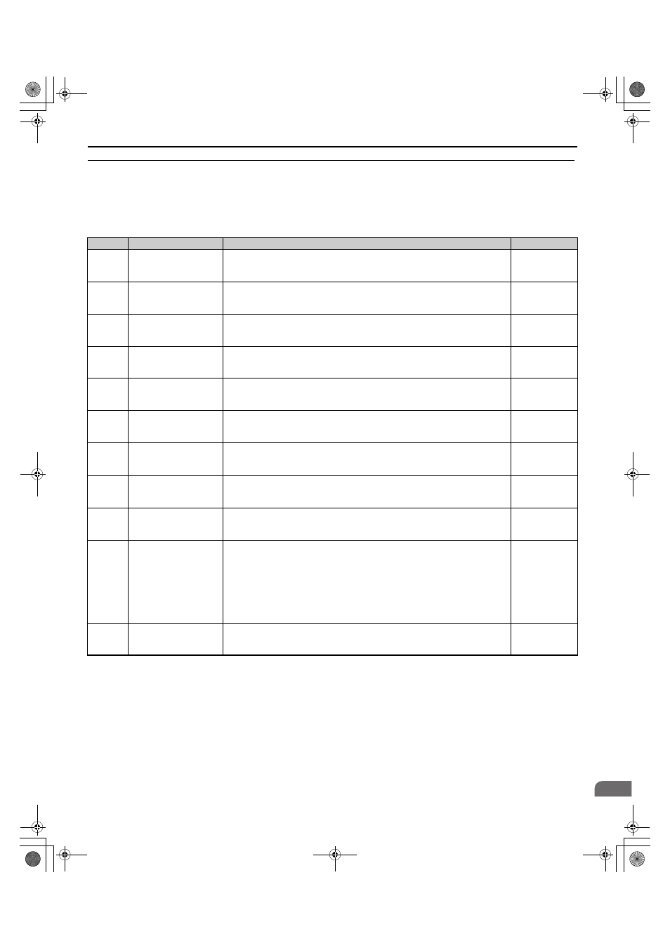
S: elevator parameters, S1: brake sequence – Yaskawa CIMR-LU Drives User Manual
Page 199

B Parameter Table
YASKAWA ELECTRIC TOEP C710616 38F YASKAWA AC Drive L1000A Quick Start Guide
199
Par
ame
te
r Ta
ble
B
◆ S: Elevator Parameters
This section describes various functions and faults needed to operate an elevator application: braking sequence, slip
compensation for elevators, start/stop optimization, Rescue Operation, and elevator-related faults.
■
S1: Brake Sequence
No.
Name
Description
Setting
S1-01
<5> Default setting is determined by the control mode (A1-02).
<39> Available in drive software versions PRG: 7016 or later.
<44> Available in drive software versions PRG: 7017 or later.
Zero Speed Level at Stop
Determines the speed to begin applying DC Injection (or Position Lock) when the
drive is ramping to stop (b1-03 = 0). Set as a percentage of the maximum output
frequency (E1-04).
Min: 0.000%
Max: 9.999%
S1-02
DC Injection Current at
Start
Determines the amount of current to use for DC Injection at start. Set as a percentage
of the drive rated current.
Default: 50%
Min: 0%
Max: 100%
S1-03
DC Injection Current at
Stop
Determines the amount of current to use for DC Injection at stop. Set as a percentage
of the drive rated current.
Default: 50%
Min: 0%
Max: 100%
S1-04
DC Injection/Position
Lock Time at Start
Determines how long the drive should perform DC Injection at start. In CLV and
CLV/PM, S1-04 determines how long Position Lock should be performed. A setting
of 0.00 disables S1-04.
Default: 0.40s
Min: 0.00 s
Max: 10.00 s
S1-05
DC Injection/Position
Lock Time at Stop
Determines how long the drive should perform DC Injection at stop. In CLV and
CLV/PM, S1-05 determines how long Position Lock should be performed. A setting
of 0.00 disables S1-05.
Default: 0.60s
Min: 0.00 s
Max: 10.00 s
S1-06
Brake Release Delay Time
Determines the delay time between the start of DC injection/Position Lock and setting
the brake control command (H2-
=50) in order to release the brake at the
beginning of the ride.
Default: 0.20s
Min: 0.00 s
Max: 10.00 s
S1-07
Brake Close Delay Time
Determines the delay time between reaching Zero Speed (S1-01) and resetting the
brake control command (H2-
= 50) in order to apply the brake at the end of the
ride.
Default: 0.10s
Min: 0.00 s
Max: [S1-05]
S1-10
Run Command Delay
Time
Sets the time that must pass after the Up/Down command is entered until the drive
internal Run command is set and the ride is started.
Default: 0.10s
Min: 0.00 s
Max: 1.00 s
S1-11
Output Contactor Open
Delay Time
Determines the delay time between shutting off the output of the drive and resetting
the contactor control command (H2-
= 51) in order to release the motor contactor
after a ride has finished.
Default: 0.10s
Min: 0.00 s
Max: 1.00 s
S1-12
Motor Contactor Control
During Auto-Tuning
Determines the state of the output contactor control command (H2-
= 51) during
Auto-Tuning.
0: Disabled
1: Enabled
2: Enabled during Auto-Tuning and HBB
Note: Setting 2 is available in the control mode CLV or CLV/PM for drives with
software versions PRG: 7017 or later. The setting is 0 or 1 for software version PRG:
7016.
Default: 0
Min: 0
Max: 2
S1-26
Emergency Stop Start
Level
Sets the Emergency Stop Start Level as a percentage of the Maximum Output
Frequency.
Default: 10.0%
Min: 0.0%
Max: 100.0%
TOEP_C710616_38F_5_0.book 199 ページ 2013年12月4日 水曜日 午前9時56分