Pass through the opening provided, Refer to wiring the main circuit terminal on, Refer to – Yaskawa CIMR-LU Drives User Manual
Page 46
3 Electrical Installation
46
YASKAWA ELECTRIC TOEP C710616 38F YASKAWA AC Drive L1000A Quick Start Guide
Wiring the Main Circuit Terminal
WARNING! Electrical Shock Hazard. Shut off the power supply to the drive before wiring the main circuit terminals. Failure to comply
may result in death or serious injury.
Wire the main circuit terminals after the terminal board has been properly grounded.
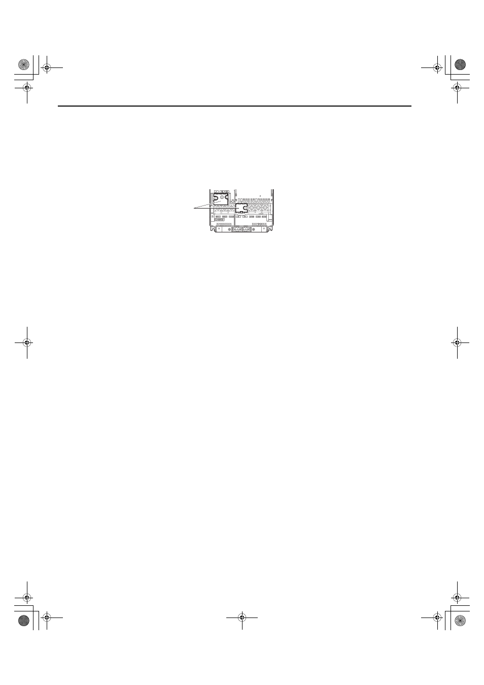
Models CIMR-LU2A0008 to 2A0075, 4A0005 to 4A0039, and 5A0003 to 5A0027 have a cover placed over the DC bus
and braking circuit terminals prior to shipment to help prevent miswiring. Use wire cutters to cut away covers as needed
for terminals.
Figure 24
Figure 24 Protecting Cover to Prevent Miswiring (CIMR-LU2A0047)
Main Circuit Connection Diagram
when wiring terminals on the main power circuit of the drive.
WARNING! Fire Hazard. The braking resistor connection terminals are B1 and B2. Do not connect braking resistors to any other
terminals. Improper wiring connections could cause the braking resistor to overheat and cause death or serious injury by fire. Failure to
comply may result in damage to the braking circuit or drive.
Refer to Standard Connection Diagram on page 25
when wiring the drive control circuit terminals.
■
Control Circuit Terminal Block Functions
Drive parameters determine which functions apply to the multi-function digital inputs (S3 to S8), multi-function digital
outputs (M1 to M6), multi-function photocoupler outputs (P1-C1, P2-C2), multi-function analog inputs (A1, A2), and
multi-function analog monitor output (FM, AM). The default setting is listed next to each terminal in
on page
NOTICE: Equipment Hazard. Improper equipment sequencing could shorten useful life of the electrolytic capacitors and circuit relays
of the drive. Refrain from switching an input contactor more often than once every 30 minutes. Normally the drive I/O should be used to
stop and start the motor.
WARNING! Sudden Movement Hazard. Always check the operation and wiring of control circuits after being wired. Operating a drive
with untested control circuits could result in death or serious injury.
WARNING! Sudden Movement Hazard. Confirm the drive I/O signals and external sequence before starting test run. Failure to comply
may result in death or serious injury.
NOTICE: Frequently switching the drive power supply to stop and start the motor can damage the drive.
NOTICE: To get the full performance life out of the electrolytic capacitors and circuit relays, refrain from switching the drive power
supply off and on more than once every 30 minutes. Frequent use can damage the drive. Use the drive to stop and start the motor.
Note: Do not solder the ends of wire connections to the drive. Soldered wiring connections can loosen over time. Improper wiring
practices could result in drive malfunction due to loose terminal connections.
A – Protecting Cover
A
TOEP_C710616_38F_5_0.book 46 ページ 2013年12月4日 水曜日 午前9時56分