Encoders – Hypertherm V9 Series Phoenix Rev.11 User Manual
Page 209
Phoenix 9.76.0 Installation and Setup Manual 806410
209
9 – Motion Control
Encoders
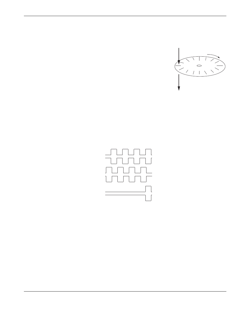
An encoder is a feedback device that provides signal pulses as the
motor turns. The diagram at the right illustrates the basic concept of an
encoder. Although this does not represent all encoder feedback device
technology, this illustration provides a visual aid to help understand the
process.
The illustration shows a disk with small holes cut out along the outer
edge. The light source projects a beam of light downward through the
holes in the disk. As the disk turns on the end of the motor shaft, the light
passes through the disk and creates pulses. The receiver below the disk
picks up the light pulses and sends that feedback to the control.
There is a direct relationship between the rotation of the motor shaft, the
encoder light pulses, and the distance of the motion. Therefore, the
control is able to calculate distance by counting the encoder pulses it
receives, which closes the position loop. This relationship, shown as a simplified formula is:
encoder pulses x motor revs = distance
The encoder generates a square wave signal as illustrated in the Encoder Signal diagram to the right. Most encoders
provide two main signals, A and B, and the complements, A/ and B/. These signals are also referred to as channels. The
compliment channels are not always used but if they are used, they can provide increased noise immunity. The rotational
direction, or encoder polarity, can be determined by the signal that is received, either ABABA or BABAB.
The channel Z signal is produced only once a revolution and is called the
marker pulse. This marker pulse is quite often
used for accuracy in homing routines.
The pulses are called
counts. The holes in the disk are also called lines. The pulses that the receiver picks up may actually
be the beginning and end of each pulse for a line on both channels (A&B) so that the receiver picks up four pulses for
each line. This is called a 4x mode encoder. Thus, a 1000 line encoder in 4x mode would produce 4000 counts for each
revolution of the motor. The more counts an encoder produces, the more accurate the motion is.
Receiver
Light source
Channel A
Channel A/
Channel B
Channel B/
Channel Z
Channel Z/