Hypertherm V9 Series Phoenix Rev.11 User Manual
Page 226
226
Phoenix 9.76.0 Installation and Setup Manual 806410
10 – Motion Compensation
3. Set the Plate Size dimensions for the area that will be mapped.
4. Open the Machine screen using the password assigned to it, and choose Laser Mapping.
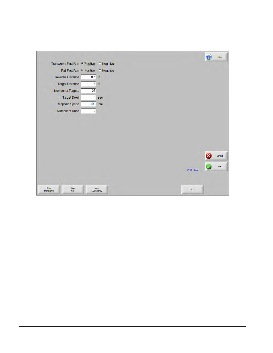
5. Use the parameters on the screen to define targets along the axis and how the laser will move between them. The
CNC uses these parameters to create a part program to control motion on each axis. These parameters are
described below.
Rail/Transverse First Run: The direction of the first run on the axis. Base the selection on the direction of
motion from home position.
Reversal Distance: The distance of travel in the opposite direction at the beginning and end of a run to
remove mechanical backlash before mapping. Reverse motion removes mechanical backlash before
mapping the axis.
Target Distance: Sets the distance between targets. Set this value in larger distances (508 mm,
20 inches) for a rough mapping and in much smaller distances (25 – 50 mm. 1 – 2 inches) for actual
mapping. A smaller distance between targets will permit more precise motion compensation.
Number of Targets: The number of positions on each run where the laser interferometer measures the
physical position of the axis. The part program that the CNC creates for mapping includes a pause at each of
these positions. Enter values between 2 and 1000. A larger number of targets will permit more precise
motion compensation.