Two-torch oxyfuel system diagram – Hypertherm V9 Series Phoenix Rev.11 User Manual
Page 261
Phoenix 9.76.0 Installation and Setup Manual 806410
261
15 – Oxyfuel Application
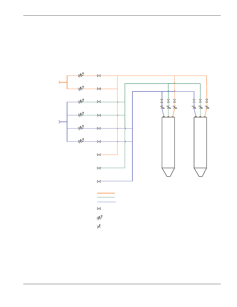
Two-torch oxyfuel system diagram
The following picture shows a sample two-torch oxyfuel system with three gas channels.
Note: This picture is a functional drawing and is not intended as a recommendation for system design. You will
need to procure components that are rated for your individual cutting system and your production needs.
Low preheat fuel
High preheat fuel
Low preheat oxygen
High preheat oxygen
Pierce oxygen
Cut oxygen
Fuel gas
supply
Oxygen gas
supply
Bleed-off fuel
Bleed-off pierce oxygen
Bleed-off cut oxygen
Fuel gas
Preheat oxygen
Cut oxygen
Gas solenoid valve, normally closed
Manual pressure regulator
Flow control valve
Each torch has its own supply lines:
Cut oxygen 1 and 2
Preheat oxygen 1 and 2
Fuel one and 2
Torch 1
Torch 2