2 – machine setup – Hypertherm V9 Series Phoenix Rev.11 User Manual
Page 61
Phoenix 9.76.0 Installation and Setup Manual 806410
61
2 – Machine Setup
Derivative Gain: Derivative gain helps to minimize sudden changes in velocity. The higher the derivative gain, the slower
the response time to the control loop. For most velocity loop drives, this parameter is set to zero (0).
Feedforward Gain: Feedforward gain can be used to drive the following error to zero during machine motion. In all
digital control loops there is a finite amount of error that is introduced by the velocity command. Increasing
feedforward gain can reduce this introduced error.
Velocity Gain: When you use a current loop amplifier, you can use the internal velocity loop in the CNC to provide
dampening without an external tachometer.
Use of the internal velocity loop with a current loop amplifier can result in higher static stiffness, smoother
machine motion, and less overshoot.
Servo Error Tolerance: Servo error, also called following error, is the difference between the commanded motor
position and the actual motor position. The servo error tolerance is the upper limit of the amount of following
error allowed before the CNC faults.
The amount of servo error tolerance depends on the cutting system mechanics. Setting the servo error
tolerance too low could cause the CNC to fault repeatedly. Setting it too high could cause inaccurate
motion or mechanical harm. Set the Following Error parameter in the Watch window and observe
steady-state operation of the cutting system (some following error is normal). Set the servo error tolerance to
a value slightly higher than the steady-state following error.
Encoder Counts per mm (inch): To determine the encoder counts per mm (inch), you will need to know the following
measurements for your encoders:
counts per revolution of the motor
gear ratio
distance of travel in one revolution of the pinion gear
diameter of the pinion gear when it engages the rack
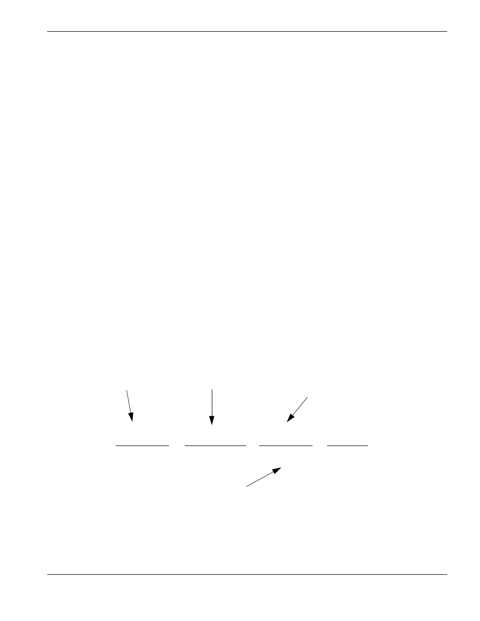
An example of the equation is shown below:
Fault Ramp Time: This parameter sets the motion deceleration time after a fault occurs. At the end of Fault Ramp Time
the drives will be disabled.
4000 counts
x
10 rev of motor
x
1 rev
=
X counts
1 revolution
1 rev of pinion
2
Π inches
inches
1000 line encoder multiplied
by 4 (quadrature) per 1 motor
revolution
10:1 gear ratio
Distance traveled in one
revolution of the pinion
Circumference of pinion (2 inch
diameter multiplied by
pi)
Encoder counts per unit
(inches or mm)