Hypertherm V9 Series Phoenix Rev.11 User Manual
Page 76
76
Phoenix 9.76.0 Installation and Setup Manual 806410
2 – Machine Setup
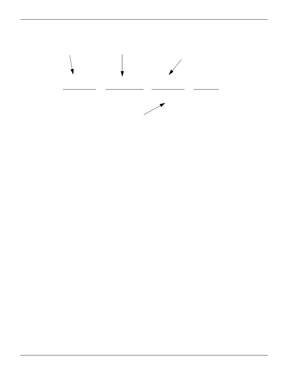
An example of the equation is shown below:
Fault Ramp Time: This parameter sets the motion deceleration time after a fault occurs. At the end of “Fault Ramp Time,
The drives will be disabled.
Drive Type: This parameter is used to tell the CNC what type of control loop to run.
If you are running an external velocity loop drive (indicated by having an integrated tachometer in the motor),
select Velocity. If you are running in torque mode (no tachometer), select Current.
DAC Polarity: This parameter allows changing of the analog output polarity to establish proper control loop feedback
without any wiring changes.
Encoder Polarity: This parameter allows changing of the encoder input polarity to establish proper counting for positive
machine motion without any wiring changes.
Encoder Decode Mode: Currently the CNC only supports 4X encoder decode mode. This has been done to increase
positional accuracy.
Use Hardware Overtravels: Select whether the cutting system will be using hardware overtravel switches. If Hardware
overtravel switches are used, the CNC will disable feedback and display an error message if the inputs
become active. It is recommended that hardware overtravel switches be installed.
Backlash Compensation: The Backlash Compensation parameter is used to offset or compensate for any backlash in
the mechanics of the drive system.
Minimum Head Spacing: Sets the minimum distance that is allowed between the Transverse 1 and Transverse 2 axes.
Home: The Home parameter is used to activate use of the Home feature. Depending on configuration, the table may be
Homed to either a designated Home Switch or an Overtravel Switch.
The Home feature is used to set a known absolute physical position location on the cutting table that is used
for referencing future manual Go to Home and other motion commands. This is generally performed through
activation of a home switch positioned on the appropriate axis giving it a known physical location.
4000 counts
x
10 rev of motor
x
1 rev
=
X counts
1 revolution
1 rev of pinion
2
Π inches
inches
1000 line encoder multiplied
by 4 (quadrature) per 1 motor
revolution
10:1 gear ratio
Distance traveled in one
revolution of the pinion
Circumference of pinion (2 inch
diameter multiplied by
pi)
Encoder counts per unit
(inches or mm)