Mstp configuration example, Network requirements, Configuring switch a – H3C Technologies H3C WX3000E Series Wireless Switches User Manual
Page 182
169
MSTP configuration example
Network requirements
As shown in
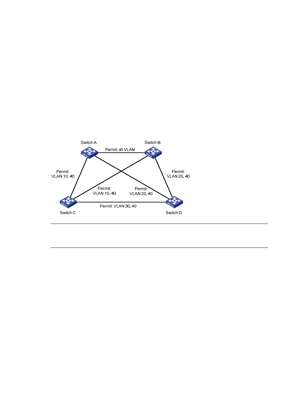
, to enable packets of different VLANs to be forwarded along different MSTIs,
perform the following configurations:
•
All devices on the network are in the same MST region.
•
Packets of VLAN 10, VLAN 20, VLAN 30, and VLAN 40 are forwarded along MSTI 1, MSTI 2,
MSTI 3, and MSTI 0 respectively.
•
Switch A and Switch B operate at the distribution layer; Switch C and Switch D operate at the
access layer. VLAN 10 and VLAN 20 are terminated on the distribution layer devices, and VLAN
30 is terminated on the access layer devices, so the root bridges of MSTI 1 and MSTI 2 are Switch
A and Switch B respectively, and the root bridge of MSTI 3 is Switch C.
Figure 153 Network diagram
NOTE:
"Permit:" next to a link in the figure is followed by the VLANs the packets of which are permitted to pass
this link.
Configuring Switch A
1.
Configure an MST region:
a.
Select Network > MSTP from the navigation tree to enter the default MSTP region page.
b.
Click Modify as shown in
.