Igmp snooping configuration example, Network requirements, Configuring router a – H3C Technologies H3C WX3000E Series Wireless Switches User Manual
Page 242: Configuring switch a
229
Field Description
Group Address
Multicast group address
Router Port(s)
All router ports
Member Port(s)
All member ports
IGMP snooping configuration example
Network requirements
•
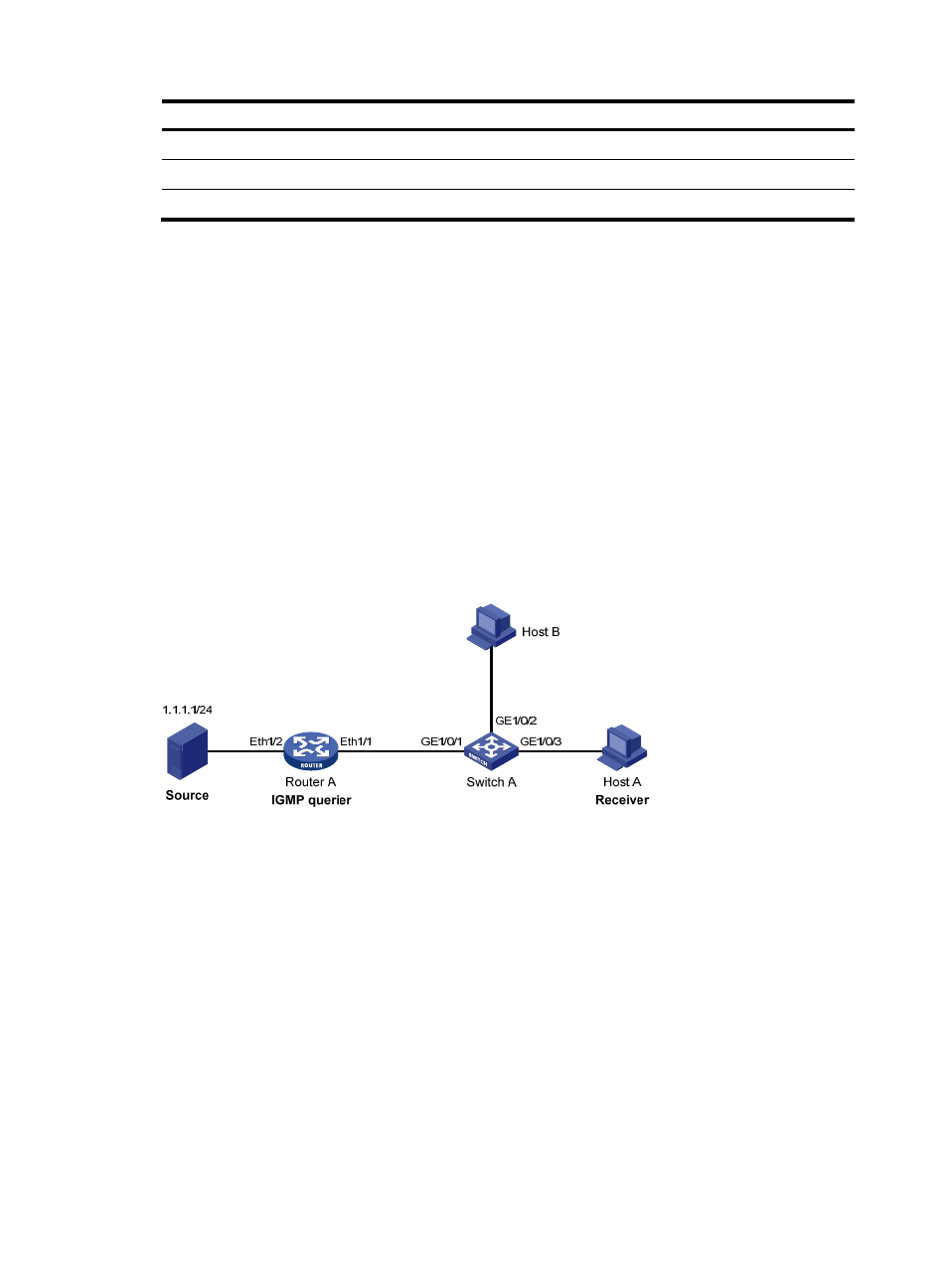
As shown in
, Router A connects to a multicast source (Source) through Ethernet 1/2,
and to Switch A through Ethernet 1/1.
•
The multicast source sends multicast data to group 224.1.1.1. Host A is a receiver of the multicast
group.
•
IGMPv2 runs on Router A and IGMP snooping version 2 runs on Switch A.
•
The function of dropping unknown multicast packets is enabled on Switch A to prevent Switch A
from flooding multicast packets in the VLAN if no corresponding Layer 2 forwarding entry exists.
•
The fast leave function is enabled for GigabitEthernet 1/0/3 on Switch A to improve bandwidth
and resource usage.
Figure 204 Network diagram
Configuring Router A
Enable IP multicast routing, enable PIM-DM on each interface, and enable IGMP on Ethernet 1/1.
(Details not shown)
Configuring Switch A
1.
Create VLAN 100:
a.
Select Network > VLAN in the navigation tree.
b.
Click the Create tab.
c.
Enter 100 as the VLAN ID.
d.
Click Create.