Feedback device – Yaskawa iQpump Programming Manual User Manual
Page 14
14
YASKAWA
TM.iQp.02 iQpump Drive Programming Manual
■
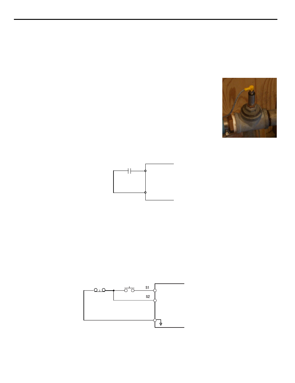
Feedback Device
The iQpump Controller requires a feedback device (e.g. Pressure transducer, flow meter, etc.) to perform automatic system regulation.
Any analog 0~10 V or 4-20 mA feedback device can be used in combination with the iQpump controller.
Connecting Your Feedback Device to the iQpump Controller
Note: The factory default setting for the iQpump controller is 4~20 mA feedback device connected to
analog input A2.
To successfully operate the iQpump drive remotely, an external run command must be received by the
Drive. Parameter b1-02 specifies from where the run command will be accepted.
Although the Run Source and the Reference Source (b1-01) are normally taken from the same source (e.g.
digital operator, terminals or serial communication), this is not always the case.
To issue a run command from the digital operator: Set b1-02 = “0: Operator,” and use the HAND and
OFF buttons to start and stop the Drive.
To issue the run command from the terminals: Set b1-02 = “1: Terminals,” and select between 2-wire
and 3-wire control operation by doing the following:
2-Wire Control The factory default setting is for 2-wire operation. In the 2-wire configuration a closure between S1 and SN will be
interpreted as a Forward Run command by the Drive.
Figure 1.7
Figure 7 2-Wire Control
3-Wire Control When any of the multi-function digital input parameters, H1-01 through H1-05, is set to 0, terminals S1 and S2 become
Run and Stop, respectively. The multi-function digital input that was set to 0 will function as a Forward/Reverse input for the iQpump
Drive. When the Forward/Reverse input is open the iQpump drive will run in the Forward direction and when the input is closed, the
iQpump drive will run in the Reverse direction.
In 3-wire operation a momentary closure (> 50mS) of S1 will cause the iQpump drive to run provided that S2 is held closed. The iQpump
drive will stop anytime the S2-SN connection is broken. If the 3-wire configuration is implemented via a 3-wire Initialization (A1-03 =
“3330: 3-Wire Initial”), then terminal S3 becomes the Forward/Reverse input.
Note: Reverse operation is disabled in the iQpump drive; however, in 3-wire control, one of the multi-function digital inputs
needs to be programmed to 0. Otherwise, the 3-wire control will not work.
Figure 1.8
Figure 8 3-Wire Control
To issue a run command via serial communication: Set b1-02 = “2: Serial Com” and connect the RS-485/422 serial communication
cable to R+, R-, S+, and S- on the removable terminal block.
• Modbus Plus Option Card CM071
Manual: IG.AFD.17
• Modbus TCP/IP Option Card CM090
Manual: IG.AFD.25
• EtherNet/IP Option Card CM092
Manual: IG.AFD.26
S1
S2
SN
FWD Run/Stop
REV Run/Stop
3-wire control
Stop switch
(NC contact)
Operation switch
(NO contact)
Run command
(run on momentary close)
Stop command
(stop on momentary open)
Sequence input common
SN